MI-1071 20
In reassembly,
mount flywheel immediately after crank-
shaft is mounted; be sure woodruff key is in position
on shaft.
Do not
drive flywheel on to taper of crank-
shaft and
do not
overtighten flywheel nut. Simply turn
nut until lockwasher collapses. Then, after end play
is set,
(see End Play paragraph)
tighten flywheel nut
by placing wrench on nut and giving handle of wrench
1 or 2 sharp blows with a soft hammer. If torque
wrench is available, tighten
50 to 55 ft. lbs.
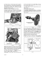
GEAR COVER (Fig’s. 29, 30 and 31)
Remove six capscrews holding gear cover in place and
drive out two
dowel pins
from crankcase side. Tap
gear cover with soft hammer at oil filler boss.
Caution:
Steel ball for crankshaft end thrust will probably fall
out when gear cover is removed. Take out thrust spring
from end of camshaft and remove flyweight assembly
from governor shaft.
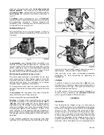
In reassembly,
insert thrust spring into end of cam-
shaft and mount governor flyweight assembly. Lubricate
bearings, gear train and tappets.
Tap dowel pins into gear cover until they extend about
1/8” past the flange face. Place a dab of low melting
grease into hole of rear cover to retain camshaft
thrust spring ball in place. Lubricate lip of oil seal
and add a light film of oil to gear cover face to hold
gasket in place.
Place oil seal sleeve,
Fig 31
, on to crankshaft, drop
steel ball into grease filled hole and assemble gear
cover by tapping in place with a soft hammer.
Caution: Be sure timing marks on crankshaft and
camshaft gear, Fig. 38, remain correctly mated
when end of camshaft is pressed into bearing hole
of gear cover.
Note:
Governor lever must be leaning in a direction
toward the engine, as shown in
Fig. 30.
This position
will prevent the internal governor vane from becoming
entangled with the governor flyweights.
Remove oil seal sleeve, tighten gear cover capscrews
to
8 ft. lbs. torque
and hammer dowel pins in place.
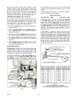
CONNECTING ROD and PISTON (Fig’s 32, 33, 34)
By means of a 1/2” socket wrench, loosen and remove
connecting rod bolts, and take off connecting rod cap.
Scrape off all carbon deposits that might interfere with
removal of piston from upper end of cylinder. Turn
crankshaft until piston is at top, then push connect-
ing rod and piston assembly upward and out thru top
of cylinder.
The piston skirt is
cam-ground
to an elliptical con-
tour. Clearance between the piston and cylinder must
be measured at the bottom of the piston skirt thrust
face. Refer to Chart
, Fig. 33,
for proper clearance.
The thrust face on the piston skirt is 90° from the
axis of the piston pin hole.
In reassembly;
use a ring compressor and stagger the
piston ring gaps 90° apart around the piston. Oil the
piston, rings, wrist pin, rod bearings and cylinder
walls before assembly.
Note:
Mount piston and rod assembly with the cast
arrow
on the connecting rod bolt boss facing towards
the open end of the crankcase, and the
oil hole
in
Содержание Air Cooled TR-10D
Страница 6: ...MI 937 2 4 Fig 1 289860C TAKE OFF rear and LEFT HAND SIDE VIEW of ENGINE...
Страница 7: ...5 MI 938 2 FAN END front and RIGHT HAND SIDE VIEW of ENGINE...
Страница 8: ...MI 939 2 6 SECTIONAL VIEWS OF ENGINE...
Страница 28: ......
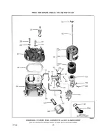
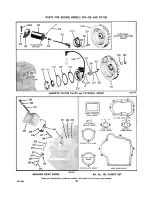
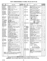
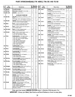
Страница 29: ...PARTS FOR ENGINE MODELS TRA 10D AND TR 10D...
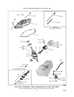
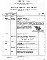
Страница 30: ...PARTS FOR ENGINE MODELS TRA 10D AND TR 10D...
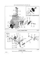
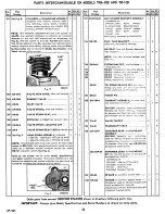
Страница 31: ...PARTS FOR ENGINE MODELS TRA 10D AND TR 10D...
Страница 32: ......
Страница 33: ......
Страница 34: ......
Страница 35: ......
Страница 36: ......
Страница 37: ......
Страница 38: ......
Страница 39: ......
Страница 40: ......
Страница 44: ......
Страница 46: ...WISCONSIN MOTOR CORPORATION MILWAUKEE WISCONSIN 532466 PRINTED IN U S A...


