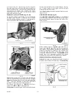
17 MI-1068
ances between the various operating parts.
DRAIN OIL FROM CRANKCASE
BEFORE DISASSEMLY
ACCESSORIES
Remove muffler and disconnect ignition wire from
spark plug. If engine is to be completely overhauled,
remove all accessories.
On engines equipped with a combination
motor-genera-
tor;
disconnect wires and adjusting strap at the genera-
tor. Remove bracket and motor-generator from side of
crankcase as a complete unit.
Caution:
In reassembly, do not put too much tension
on drive belt.
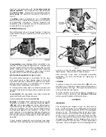
FUEL TANK (Fig. 19)
Close fuel valve in tank and disconnect fuel line at
carburetor. Remove two capscrews holding fuel tank
bracket to crankcase, and take out the two screws
holding tank bracket and control panel (if applicable)
to cylinder head.
Fuel tank
and
bracket
can be re-
moved as a complete unit.
STARTER SHEAVE and FLYWHEEL SHROUD (Fig. 20)
Remove
starter sheave
and
screen
by taking out the
three screws and washers that mount them to the fly-
wheel. Disassemble
flywheel shroud
and
back plate
by
unhooking governor spring, and then removing two
capscrews holding shroud to bottom of crankcase and
two screws at the cylinder head.
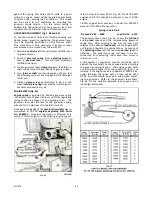
CARBURETOR and AIR CLEANER (Fig. 21)
The carburetor and air cleaner should be removed both
to facilitate working on the engine and to prevent da-
mage to these parts. Disconnect; breather line at in-
spection cover and throttle rod clip at governor lever.
Take out the two screws holding manifold to cylin-
der, and remove air cleaner, bracket, carburetor and
manifold as a complete unit.
CYLINDER HEAD and SPARK PLUG
Remove spark plug and take out remainder of cylinder
head screws. Disassemble cylinder head, gasket, cyl-
inder head cover and cylinder side shroud. Clean out
carbon from combustion chamber and dirt from between
the cooling fins.
In reassembly
, use new cylinder head and spark plug
gaskets. Mount cylinder head cover, fuel tank bracket
and cylinder head all at the same time, as these parts
are all mounted with the cylinder head capscrews. Use
the different length capscrews according to the height
of the bosses on the cylinder head.
Torque
head
screws to
18 ft. lbs
., in three alternate stages: 10 ft.
lbs., 14 ft. lbs., and finally 18 ft. lbs.
Leave spark plug off temporarily, for ease in turning
engine over for remainder of assembly and for timing
Содержание Air Cooled TR-10D
Страница 6: ...MI 937 2 4 Fig 1 289860C TAKE OFF rear and LEFT HAND SIDE VIEW of ENGINE...
Страница 7: ...5 MI 938 2 FAN END front and RIGHT HAND SIDE VIEW of ENGINE...
Страница 8: ...MI 939 2 6 SECTIONAL VIEWS OF ENGINE...
Страница 28: ......
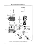
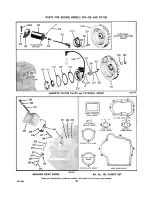
Страница 29: ...PARTS FOR ENGINE MODELS TRA 10D AND TR 10D...
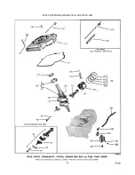
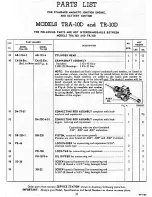
Страница 30: ...PARTS FOR ENGINE MODELS TRA 10D AND TR 10D...
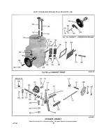
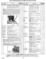
Страница 31: ...PARTS FOR ENGINE MODELS TRA 10D AND TR 10D...
Страница 32: ......
Страница 33: ......
Страница 34: ......
Страница 35: ......
Страница 36: ......
Страница 37: ......
Страница 38: ......
Страница 39: ......
Страница 40: ......
Страница 44: ......
Страница 46: ...WISCONSIN MOTOR CORPORATION MILWAUKEE WISCONSIN 532466 PRINTED IN U S A...


