7 MI-1058
GENERAL DESIGN
Wisconsin
engines are of the
four cycle type
, in which
each of the four operations of
suction, compression,
expansion
and
exhaust
constitutes a complete stroke.
This gives one power stroke for each two revolutions of
the crankshaft.
COMPRESSION RELEASE
A component part of the camshaft that operates auto-
matically and trouble free. Permits fast and effortless
starting with no dangerous “kick back”.
COOLING
Cooling is accomplished from a flow of air circulated
over the cylinder and head of the engine, by a combi-
nation fan-flywheel encased in a sheet metal shroud.
The air is divided and directed by ducts and baffle
plates to insure uniform cooling of all parts.
Never operate an engine with any part of the
shrouding removed, because this will retard the
air cooling.
Keep the cylinder and head fins free from dirt
and chaff. Improper circulation of cooling air will
cause engine to overheat.
CARBURETOR
The proper combustible mixture of gasoline and air is
furnished by a balanced carburetor, giving correct fuel
to air ratios for all speeds and loads.
IGNITION
The spark for ignition of the fuel mixture is furnish-
ed by a high tension
flywheel magneto
. A stator plate
functions as an engine bearing plate as well as a sup-
port for the coil and core. The permanent magnet is an
integral part of the flywheel, and a breaker box on the
side of the crankcase contains the points, condenser
and stop switch. A push pin, actuated by the engine
camshaft, operates the
breaker arm at half engine speed
.
Battery ignition
(12 volt) can be furnished in place of
magneto, when specified. An ignition coil and breaker
assembly are the means of inducing high voltage to
the spark plug
. Battery is not
furnished by Wisconsin
Motor Corporation.
LUBRICATION SYSTEM
An oil dipper on the connecting rod provides for a
splash type lubrication system. The action of the dip-
per striking the oil in the crankcase provides ample lub-
rication for all internal parts of the engine.
GOVERNOR
A governor of the centrifugal flyball type controls the
engine speed by varying the throttle opening to suit
the load imposed upon the engine. Manually operated
variable speed controls are available for practically
all applications.
ROTATION
The rotation of the crankshaft is
clockwise
when
viewing the flywheel or starting end of the engine.
This gives
counter-clockwise
rotation at the power
take-off end of the crankshaft.
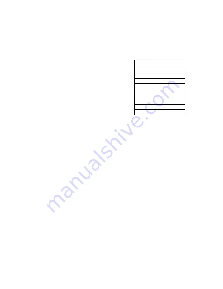
Horsepower
given in the accompanying chart is for an
atmospheric temperature of 60° Fahrenheit at sea
level and at a Barometric pressure of 29.92 inches of
mercury.
HORSEPOWER
For each inch lower the Barometric pressure drops,
there will be a loss in horsepower of 3
½
%.
For each 10° temperature rise there will be a reduce-
tion in horsepower of 1%.
For each 1000 ft. altitude above sea level there will
be a reduction in horsepower of 3
½
%.
The friction in new engines cannot be reduced to the
ultimate minimum during the regular block test, but
engines are guaranteed to develop at least 85 per
cent of maximum power when shipped from the fac-
tory. The power will increase as friction is reduced
during the first few days of operation. The engine will
develop at least 95% of maximum horsepower when
friction is reduced to a minimum.
INSTRUCTIONS FOR
STARTING AND OPERATING
LUBRICATION
Before starting a new engine, fill crankcase base with
the correct grade of engine oil, as specified in “
grade
of oil chart
”. Fill thru the dipstick plug opening illus-
trated in
Fig. 4
, with
1 quart
of oil.
For
run-in of new engines
, use same oil as recom-
mended in Grade Of Oil Chart.
The oil level mark is indicated by a groove on the dip
stick as shown in
Fig 4
. Check oil level by resting
the bottom of plug at the top of oil filler opening on
gear cover. (Do not thread in place to check level).
Too much emphasis cannot be given to the matter of
oil selection. High grade oil of the body suited to the
requirements of your engine is the most important sin-
gle item in the economical operation of the unit, yet
R.P.M
MODEL TRA-10D
2000
5.4
2200
6.1
2400
6.8
2600
7.6
2800
8.3
3000
8.8
3200
9.4
3400
9.8
3600
10.1
Содержание Air Cooled TR-10D
Страница 6: ...MI 937 2 4 Fig 1 289860C TAKE OFF rear and LEFT HAND SIDE VIEW of ENGINE...
Страница 7: ...5 MI 938 2 FAN END front and RIGHT HAND SIDE VIEW of ENGINE...
Страница 8: ...MI 939 2 6 SECTIONAL VIEWS OF ENGINE...
Страница 28: ......
Страница 29: ...PARTS FOR ENGINE MODELS TRA 10D AND TR 10D...
Страница 30: ...PARTS FOR ENGINE MODELS TRA 10D AND TR 10D...
Страница 31: ...PARTS FOR ENGINE MODELS TRA 10D AND TR 10D...
Страница 32: ......
Страница 33: ......
Страница 34: ......
Страница 35: ......
Страница 36: ......
Страница 37: ......
Страница 38: ......
Страница 39: ......
Страница 40: ......
Страница 44: ......
Страница 46: ...WISCONSIN MOTOR CORPORATION MILWAUKEE WISCONSIN 532466 PRINTED IN U S A...


