MI-1073 22
as shown in
Fig. 35
. Spread ring only far enough to
slip over piston and into correct groove, being care-
ful not to distort ring. The word
‘top’
, stamped on the
compression and scraper rings, indicates the proper
mounting of these two rings.
See Fig. 36
for correct
placement of all three rings.
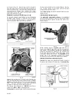
CAMSHAFT and VALVE TAPPETS (Fig’s. 37, 38)
To prevent tappets from falling out and becoming
damaged when camshaft is removed, turn crankcase
over on its side as shown in
Fig. 37
. Push tappets in-
ward to clear cam lobes, and remove camshaft.
Note:
Withdraw tappets and mark then for identification
with the hole that they were removed from.
In reas-
sembly,
put tappets back in their corresponding guide
hole. This will eliminate unnecessary valve stem
grinding for obtaining correct tappet clearance.
The tappet stem diameter is
.309/.310
, and has a
clearance of
.002
to
.006”
in the guide hole.
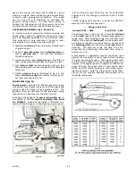
Timing mark
on camshaft gear must be located between
the two marked teeth on the crankshaft gear. See
Fig.
38
. If valve timing is off, engine will not function
properly or may not run at all.
Insert
thrust spring
into end of camshaft before mount-
ing gear cover.
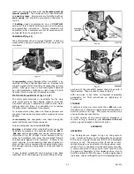
COMPRESSION RELEASE (Fig. 39)
The
automatic compression release
is incorporated
with the engine camshaft, and with the proper engine
maintenance should operate trouble free, with a min-
imum of wear.
While cranking engine, a
spoiler cam
holds the ex-
haust valve slightly open thru part of the compres-
sion stroke. This condition reduces the compression
pressure, allowing the engine to be turned over
faster and with less effort. After the engine starts
and speed reaches 650 R.P.M., the
flyweight
places
spoiler cam in an inoperative position and normal
compression is returned to the combustion chamber.
BREAKER PUSH PIN and BUSHING (Fig. 40)
Push pin
for breaker arm should be removed, inspected
for wear and replaced if necessary.
In reassembly:
Содержание Air Cooled TR-10D
Страница 6: ...MI 937 2 4 Fig 1 289860C TAKE OFF rear and LEFT HAND SIDE VIEW of ENGINE...
Страница 7: ...5 MI 938 2 FAN END front and RIGHT HAND SIDE VIEW of ENGINE...
Страница 8: ...MI 939 2 6 SECTIONAL VIEWS OF ENGINE...
Страница 28: ......
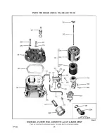
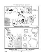
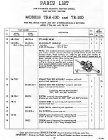
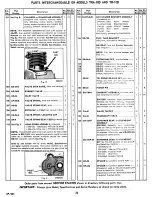
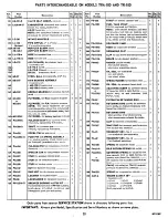
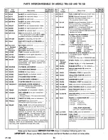
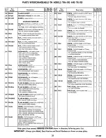
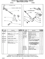
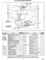
Страница 29: ...PARTS FOR ENGINE MODELS TRA 10D AND TR 10D...
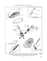
Страница 30: ...PARTS FOR ENGINE MODELS TRA 10D AND TR 10D...
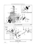
Страница 31: ...PARTS FOR ENGINE MODELS TRA 10D AND TR 10D...
Страница 32: ......
Страница 33: ......
Страница 34: ......
Страница 35: ......
Страница 36: ......
Страница 37: ......
Страница 38: ......
Страница 39: ......
Страница 40: ......
Страница 44: ......
Страница 46: ...WISCONSIN MOTOR CORPORATION MILWAUKEE WISCONSIN 532466 PRINTED IN U S A...


