background image


30


12.1" Vehicle Mount Computer FM12Q Product Reference Guide 

2.17.2 USB Keyboard/ Mouse 

A standard USB keyboard or mouse can be attached to the FM12Q using the appropriate adapter 

cable. The cable attached to the device and provides USB connector. 


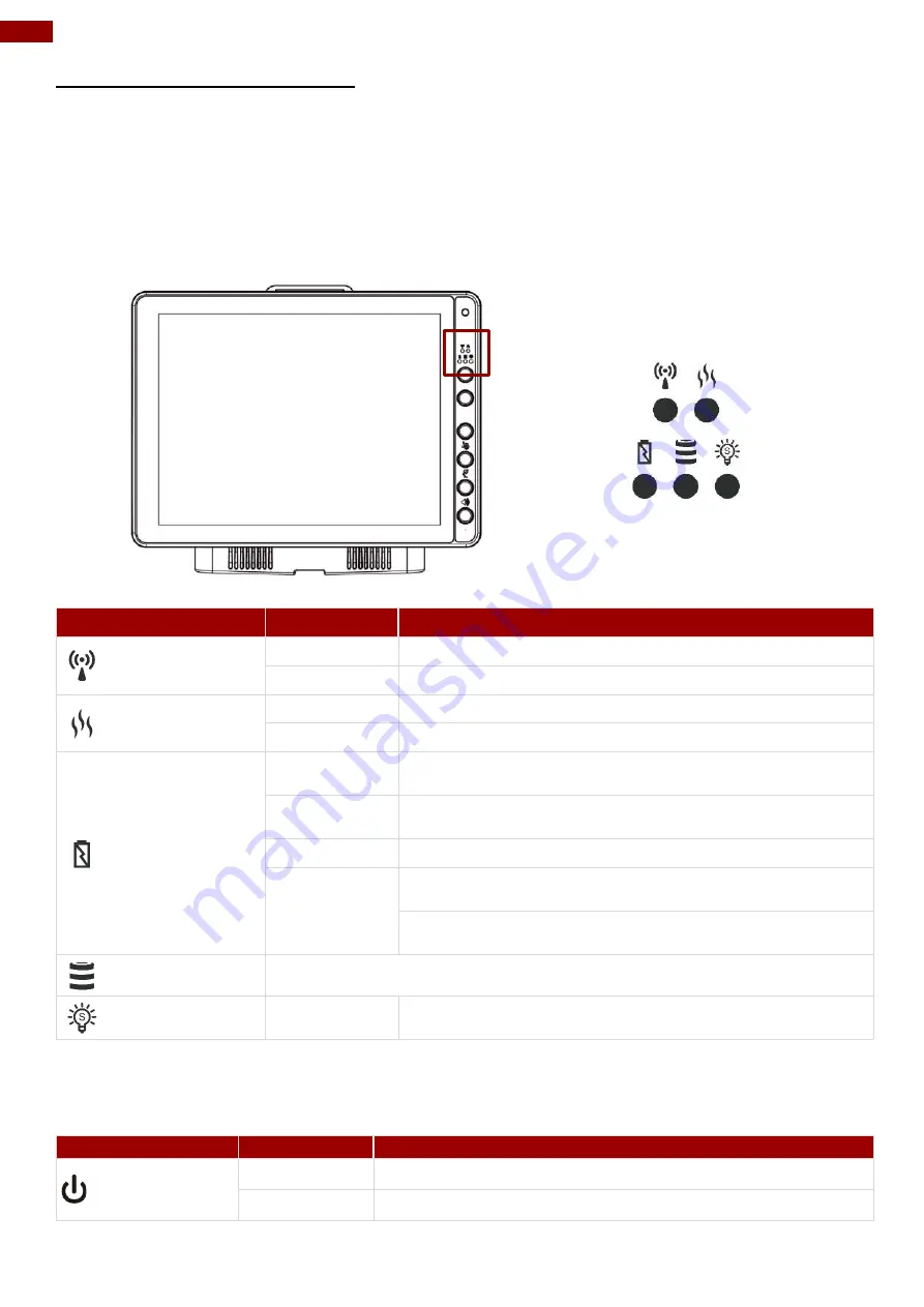
2.18 LED Function 

LED indicators are located on the front panel with the left and right sides. 


Indicator Type 

LED Behavior  System State 

 WLAN 

ON 

The Device has detected a network and is connecting 

OFF 

No Network connection 

Defroster Indicators 

Solid Red 

The Defroster is ON 

OFF 

The Defroster is OFF 

UPS Battery 

Orange 

The external power is plugged in and the UPS battery is 
being charged 

Green 

The UPS battery is in use and its power level is more than 
10% 

Blinking Red 

The UPS battery is low (<10%) 

OFF 

The external power is plugged in and the UPS battery is 
fully charged 
The device is mounted on the vehicle dock and the UPS 
battery is fully charged 

HDD Indicators 

Default setting is no function 

Light Sensor 

Light  sensor automatically adjusts the panel brightness 
based on the light settings. 

Note:


Defroster is a customized feature available by request. 

Note:


For the defroster function, please connect a device to a power supply. 


Power LED is located on the power button. Power LED behavior is shown at the table below. 

Indicator Type 

LED Behavior  System State 

  Power 

Solid Red 

System off and in suspend mode 

OFF 

System On 


Содержание FM12Q

Страница 1: ...ese instructions carefully before using this product and save this manual for future use Vehicle Mounted Computer Qualcomm Snapdragon 660 octa core 2 2 GHz FM12Q User Manual Version 1 2 Document Part No 9152111I109J ...

Страница 2: ......

Страница 3: ...2 9 4 Turn Off 17 2 10 Power Control 17 2 10 1 Power Switch 17 2 10 2 Power Button 17 2 11 Ignition Control 18 2 12 Battery 18 2 12 1 UPS Battery 19 2 12 2 Backup Battery 19 2 13 External Connectors 20 2 13 1 Connector Pin Assignment 21 2 14 CANBus Cable Installation Reference 27 2 15 Antenna Connections 28 2 16 External Vehicle Remote Antenna 28 2 17 Keyboard Options 29 2 17 1 Integrated Keypad 2...

Страница 4: ... Software Update 67 3 13 1 Image Tool Download 67 3 13 2 OTA Update Guide 68 3 14 Transfer Files via USB 72 3 15 Changing Touchscreen Modes 76 Chapter 4 Accessories Installation 78 4 1 Installing a SIM Card 78 4 2 Installing a Micro SD Card 79 4 3 Installing a Stylus with the holder 80 Chapter 5 Vehicle Mounting 81 5 1 Introduction 81 5 2 Vehicle Mount Instruction 81 5 3 RAM Mount Installation 82 ...

Страница 5: ...s no responsibility or liability for the use of the described product s conveys no license or title under any patent copyright or masks work rights to these products and makes no representations or warranties that these products are free from patent copyright or mask work right infringement unless otherwise specified Applications that are described in this guide are for illustration purposes only ...

Страница 6: ... and found to comply with the limits for a Class B digital device pursuant to Part 15 of the FCC Rules These limits are designed to provide reasonable protection against harmful interference in residential installation This equipment generates uses and can radiate radio frequency energy and if not installed and used in accordance with the instructions may cause harmful interference to radio commun...

Страница 7: ...tilisateur de l appareil doit accepter tout brouillage radioélectrique subi même si le brouillage est susceptible d en compromettre le fonctionnement This device complies with Industry Canada license exempt RSS standard s Operation is subject to the following two conditions 1 This device may not cause interference and 2 This device must accept any interference including interference that may cause...

Страница 8: ...ur les instructions destinés à alerter l utilisateur d un CHOC ÉLECTRIQUE mortel ou de blessure grave en cas d utilisation incorrecte de l unité SA1966 Avertissement Utilisé pour les instructions destinés à alerter l utilisateur d un risque mortel ou de blessure grave en cas d utilisation incorrecte del unité Attention Pour réduire le risque d incendie ou de choc electrique ne pas exposer l appare...

Страница 9: ...ages ou s il n est pas utilize pendant une longue période 12 Faire exécuter le service par du personnel qualifié Une intervention technique est requise lorsque l appareil a été endommagé ou n opère pas normalement Safety Information EN Follow and adhere to all warnings and instructions on the screen For your safety please read all safety and operating instructions before using the device Keep this...

Страница 10: ...ons The battery should not be damaged or crushed The battery should not be heated or exposed to direct sunlight If you are not aware of local regulations on disposing the battery pack contact our Service Center or sales representatives for more information Important This hot swap battery is soft packed It may have up to 8 inflation in dimensions under the usage in normal conditions The mechanical ...

Страница 11: ... of the warehouse and designed to fit seamlessly into forklifts and other warehouse vehicles Note Contact our technical support for information on the latest firmware upgrade for your device 1 1 About This Guide This Product Reference Guide provides instruction for the system administrator to follow when configuring and using the FM12Q Vehicle Mount Computer This Product Reference Guide has been d...

Страница 12: ...Power Cable RS232 Cable Audio Cable LAN Cable WWAN Antenna Fuse Kit Spare Key for Vehicle Dock CANBus Cable CANBus cable w o DIDO Note Notice that only one antenna is included in the package If you plan to use WWAN function please order two WWAN antennas Note Notice that in order to have sound you have to plug in the audio cable first than connect to docking ...

Страница 13: ...nsor and LED indicators Wireless communication indicators Defroster indicator Defroster is a customized feature available by request UPS battery indicators HDD indicators Light sensor 4 Power Button and Indicator Press and hold the button for 3 second to turn on the device 5 Function buttons Programmable function keys that can be configured by using the Win Set Utility Digital Microphone For voice...

Страница 14: ...75 100 and RAM Mount 3 Kensington Lock Connect to a security lock protecting your device from being stolen 4 Power switch Set the switch to on I to provide the supply power to the device and it will automatically connect to the ignition system of the vehicle Top and Bottom View No Item Description 1 Lock Lock the tablet in place 2 Reading Light Use to provide illumination in darkenvironment ...

Страница 15: ...t MicroSD card 6 Dual Nano SIM Card Slot Service window to insert Nano SIM cards 7 USB Type C A high speed USB port connects to USB devices 8 Power Input Connect a 12V DC IN power input 9 COM1 and COM2 Connect a peripheral device such as a printer or scanner with serialport 10 USB Type A x 2 Connect USB peripheral devices such as USB Flash drive mouse keyboard printer etc 11 CAN Bus Audio Connect ...

Страница 16: ...vice supports the following I O connectors 1 x Dual Nano SIM Card Slot 1 x Micro SD Card Slot 1 x USB 3 0 Type C OTG 1 x 12 V DC in power input jack Note Only Sierra Module can support dual SIM single standby function The Vehicle Dock of the FM12Q device supports the following I O connectors 2 x COM 1 x DB9 Connector for 2 x USB 2 0 Port 1 x CANBus or 1 x Audio In and Out 1 x Gigabit LAN port 1 x ...

Страница 17: ... connection your device supports Wireless Wide Area Networking WWAN 2 8 Power 2 8 1 Vehicle DC Power Supply The Power input voltage range for the vehicle dock is between 10 to 60V DC without the need to perform any manual operation within the vehicle dock This dock provides conditioned power output for the device By using a specified DC to DC adapter the input voltage of 100 240 V DC nominal can b...

Страница 18: ...icator will Off after the screen is Off the system is already in the standby sleep mode Off Wake Up Press the On button for 1 second until the screen On and then release the button Off Turn Off Press the On button for 2 second until the system is turns Off and then releases the button Off 2 9 1 Turn On When the FM12Q is attached to either vehicle power or an external power supply or it is operatin...

Страница 19: ... maintaining the date and time while the device is off 2 10 Power Control 2 10 1 Power Switch Power switch is located on the rear side of the vehicle dock When the dock is connected to the external power and the power switch is ON the dock delivers power to the FM12Q and the device can be powered on 2 10 2 Power Button Power button is located at the lower right side of the FM12Q If the device is O...

Страница 20: ...nstructions in this user manual Keep the battery away from fire Store in a cool dry place Do not expose to heat water and rain Avertissement Il existe un risque d explosion causé par une installation incorrecte ou une mauvaise utilisation de la batterie Pour éviter d éventuelles blessures Utilisez uniquement le type de batterie recommandé par Winmate Suivez les instructions d installation de la ba...

Страница 21: ...ely The internal UPS battery status LED and the UPS battery control panel can be used to monitor the status of the UPS battery Important Charge the hot swap battery together with main battery whenever your device is not being used charged for three months Connect the device to the source of power for 1 5 hours to charge Warning If you leave the device without charging for more than three months th...

Страница 22: ...nner 2 COM2 connects to a device such as printer or scanner 3 USB connects to USB devices such as USB flash drive mouse keyboard printer etc this USB also accept a dongle cable with a USB host port and a USB Client port 4 CAN Bus Audio allows direct linking into vehicle enable access to wide range of vehicle data and Audio connects to a stereo headset external speakers or audio recording device 5 ...

Страница 23: ...Output CN1 5 GND Signal Power Ground CN1 6 DSR Data Set Ready Input CN1 7 RTS Request to send Output CN1 8 CTS Clear to send Input CN1 9 5V Power CN2 Pin Signal Description CN2 1 DCD Data Carrier Detect Input CN2 2 RXD Receive Data Input CN2 3 TXD Transmit Data Output CN2 4 DTR Data Terminal Ready Output CN2 5 GND Signal Power Ground CN2 6 DSR Data Set Ready Input CN2 7 RTS Request to send Output ...

Страница 24: ...13 1 2 USB 2 0 DB9 Male Connector CN1 Pin Signal CN1 1 GND CN1 2 USB1_D CN1 3 USB1_D CN1 4 USB1_VCC CN1 5 GND CN1 6 GND CN1 7 USB2_D CN1 8 USB2_D CN1 9 USB2_VCC CN2 CN3 Pin Signal Description CN2 1 USBVCC1 Red CN2 2 USB1_DM White CN2 3 USB1_DP Green CN2 4 GND Black ...

Страница 25: ... Signal CN1 1 GND CN1 2 USB1_D CN1 3 USB1_D CN1 4 USB1_VCC CN1 5 GND CN1 6 GND CN1 7 USB2_D CN1 8 USB2_D CN1 9 USB2_VCC CN2 Pin Signal Description CN2 1 USBVCC1 Red CN2 2 USB1_DM White CN2 3 USB1_DP Green CN2 4 GND Black CN3 1 USBVCC2 Red CN3 2 USB2_DM White CN3 3 USB2_DP Green CN3 4 GND Black ...

Страница 26: ...24 12 1 Vehicle Mount Computer FM12Q Product Reference Guide CN3 Pin Signal CN3 1 GND CN3 2 USB1_D CN3 3 USB1_D CN3 4 USB1_VCC CN3 5 GND CN3 6 GND CN3 7 USB2_D CN3 8 USB2_D CN3 9 USB2_VCC ...

Страница 27: ... CN1 B CAN_V CAN3 15 5V CN2 B CAN_V CN1 C CAN_H CN3 13 CAN_H CN2 C CAN_H CN1 D CAN_L CN3 2 CAN_L CN2 D CAN_L CN1 E CAN_SHLD CN3 12 CAN_SHLD CN2 E CAN_SHLD CN3 SHELL CN3 5 GND CN3 11 GND Pin No Symbols Pin No Symbols CN2 3 MIC CN3 8 MIC_L CN2 1 GND CN3 9 AUGND CN1 1 GND CN3 1 HP_JD CN3 7 AUGND CN1 2 Right CN3 6 HP_R CN1 3 Left CN3 10 HP_L ...

Страница 28: ...ehicle Mount Computer FM12Q Product Reference Guide 2 13 1 5 LAN Connector Pin No Symbols 1 TX_D1 2 TX_D1 3 RX_D2 4 BI_D3 5 BI_D3 6 RX_D2 7 BI_D4 8 BI_D4 2 13 1 6 Power Connector 1 Power Connector 2 Power Switch ...

Страница 29: ...N2 3 VIN CN2 4 VIN CN2 5 VIN CN1 1 VIN CN2 1 VIN CN2 2 VIN CN2 6 VIN CN2 7 VIN CN2 8 IGN_ISO 2 14 CANBus Cable Installation Reference After connecting the CAN Bus cable to the FM12Q please open software utility to check settings COM1 COM2 COM3 USB CAN Bus Audio Disable CAN Bus V V V V X V Enable CAN Bus X X V V V V Note COM3 is located on the external cable supplied with the FM12Q ...

Страница 30: ... on the device and require external remote mount antennas 1 WLAN Main External Antenna Connector Default WLAN Auxiliary External Antenna Connector Default 2 GPS External Antenna Connector Optional 3 WWAN External Antenna Connector Optional 2 16 External Vehicle Remote Antenna The FM12Q vehicle dock is equipped with SMA Connector for additional external antenna WLAN or optional WWAN to install the ...

Страница 31: ...ot Tab application on the control panel See Programmable key to remap these keys The default values for these keys are Note Sign plus means that you have to press both function keys at the same time Press these keys in this order Default Key Value F1 F2 Touch Keypad Lock Unlock F2 F3 Brightness adjustment panel keypad F3 F4 Volume adjustment Long press on F1 Open WinSet Long press on F3 Lamp On Of...

Страница 32: ...r is plugged in and the UPS battery is being charged Green The UPS battery is in use and its power level is more than 10 Blinking Red The UPS battery is low 10 OFF The external power is plugged in and the UPS battery is fully charged The device is mounted on the vehicle dock and the UPS battery is fully charged HDD Indicators Default setting is no function Light Sensor Light sensor automatically a...

Страница 33: ... combined with a stylish sleek design P CAP multi touch offers fast and sensitive touch response excellent optical clarity and long term stability over temperature Note Always use the tip of the stylus for tapping or making strokes Do not use any sharp objects for tapping touching or making strokes 2 19 2 Display Backlight Control This device is equipped with automatic brightness adjustment that c...

Страница 34: ...iguration of the device might vary 3 1 1 Operating System The operating system of the FM12Q is Android 9 0 3 1 2 About Android 9 0 We assume you are very familiar with various features and options of Android OS Therefore this section will describe the specific software and utility programs that related to the device usage and the Android OS 3 2 Setting up the Device When you first turn on your dev...

Страница 35: ...ch the screen in the middle or swipe up from the bottom Many screens in apps and Settings include a menu icon at the top right of the screen Touch it to explore additional options including Help feedback To add an app to a Home screen 1 Go to the Home screen where you want to place the app 2 Swipe up 3 Swipe up and down to find the app you want 4 Touch hold the app until the Home screen appears sl...

Страница 36: ...nge frequently used settings like turning on WLAN To open Quick Settings swipe down from the top of the screen with two fingers To change a setting just touch the icon Display brightness Slide to lower or increase the brightness of your screen WLAN network Turn Wi Fi on or off or open the Wi Fi settings menu BT settings Turn Bluetooth on or off or open the Bluetooth settings menu Auto rotate Lock ...

Страница 37: ...from the right top of the screen to get the notifications area The following icons indicate the status of your device for example if users are connected to a WLAN network that is not connected to the internet the network icons are appears in white color Status icons that appear in the status bar are as follows 3 3 2 Notification Icons Pull down from the left top of the screen to get the notificati...

Страница 38: ...he touch screen These objects may scratch the screen Use only the stylus pen or the tip of your finger The touchpad supports the core gestures for Android Gesture Action Description Single Touch To select or activate something Double touch Tap quickly twice on a webpage screen or App to zoom Touch and hold Touch and hold an item on the screen by touching it and not lifting your finger until it res...

Страница 39: ...ss Pull down from the top of the screen to get the notifications area You can also access display settings in settings To adjust the brightness of the screen 1 Settings Display Brightness Level Tap the cursor to the left to reduce the screen brightness Tap the cursor to the right to increase the screen brightness ...

Страница 40: ...e The instruction for installing changing and uninstalling language in this section are applicable to FM12Q with Android OS To access region and language settings perform the following Settings System Language Input Languages The FM12Q is shipped with English language settings by default ...

Страница 41: ...39 Chapter 3 Software 3 4 2 3 Sound To access sound settings perform the following Settings Sound ...

Страница 42: ... settings 3 4 2 4 Touch Lock Press F1 and F2 simultaneously to perform touch lock While the touch is locked all function keys and touch will not be able to work until you slide the bar to unlock the touch lock Press F1 and F2 simultaneously one more time to perform unlock touch function or you can slide the bar to unlock the touch lock ...

Страница 43: ... 3 Software 3 4 2 5 Reading Lamp Long press F3 button to turn On Off a reading lamp located at the bottom of the dock This lamp is to provide illumination for user to read in the dark environment Lamp Off Lamp On ...

Страница 44: ...r on the right side of the screen Slide to the right side to increase the volume and slide to the left side to decrease the volume 3 4 2 7 Brightness Press F2 and F3 simultaneously to perform brightness adjustment The adjustment slide bar will appear on the right side of the screen Slide to the right side to increase the volume and slide to the left side to decrease the brightness ...

Страница 45: ...Cable to the FM12Q device Step 2 Touch All APPS icon and the open Ethernet application Step 3 Ethernet APP main menu appears Setting Description Check Ethernet Check Ethernet connection parameters IP mode IP address DNS address and others Configure Ethernet Enable Ethernet connection and configure its such as connection type Advanced Settings Configure advanced parameters of the Ethernet ...

Страница 46: ...e 3 5 1 Configuring Ethernet Settings Go to All Apps Ethernet Configure Ethernet Connection Type Setting Description DHCP default The device automatically capture IP address from the router Static IP Allows to manually set up IP address DNS Network and Gateway ...

Страница 47: ...45 Chapter 3 Software 3 5 2 Checking the Ethernet Settings To check Ethernet settings Go to All Apps Ethernet Check Ethernet Ethernet settings menu appears on the top right side of the desktop ...

Страница 48: ...46 12 1 Vehicle Mount Computer FM12Q Product Reference Guide 3 6 Winset 3 6 1 Winset Application Open Winset application ...

Страница 49: ...the system is powered on via ignition key the system will delay 1 second to power on Off Delay 10 seconds When the system is powered off via ignition key the system will delay 10 seconds to shut down Hard Off Delay 30 seconds When the system is powered off via ignition key the device will cut off power after 30 seconds Reset to default Resets the ignition settings back to the default Note If you d...

Страница 50: ...ditions or either one to set up the threshold Step 2 Select what action you want to perform while the threshold had been triggered Step 3 Press Set Setting Setting Options Description Blanking ON OFF Enable or disable screen blanking function Behavior Touch Lock Locks touch function Blank Screen Screen is going blank Lock and Blank Screen Locks touch function and screen is going blank Show Dialog ...

Страница 51: ...ys open Winset In Function Buttons window of the F1 click NEW to open the drop down menu of function keys In this example we have selected to set up functions for F1 function key Choose the function key and then select a Default application that will be opened by pressing on the function key you ve selected Press DEL to reset the function key to previous settings Tick the Fn Keys Lock option to di...

Страница 52: ...tery power Avertissement Le dégivreur est toujours désactivé lorsque l appareil fonctionne à partir d une alimentation par batterie UPS To use a defroster please connect a device to power supply 1 To show the defroster open Winset and this screen below shows the information about the defroster Default Settings Function Key Description On trip point 0 C Off trip point 15 C Note To complete setting ...

Страница 53: ...s selected as Defroster trip on point meaning that the Defroster will be activated when the temperature drops down to 0 C 3 To trigger the Defroster OFF the Defroster off trip point needs to be set higher than the set temperature The defroster off trip point is configurable as follow When the Defroster is OFF a defroster indicator in the lower right corner of the device will Turn off Example In th...

Страница 54: ...oster is OFF a defroster indicator in the lower right corner of the device is Turn off 3 7 Winmate Home Manager WHM Winmate FM12Q Vehicle Mounted Computer comes with preinstalled APP called Winmate Home Manager WHM which let the device manager to lock the launcher then the user can only use one application assigned by the device manager 3 7 1 How to Lock Applications 1 In the main APPS window sele...

Страница 55: ...ich app to run up automatically after booting Password Manager User can set WHM password Default password is 0000 About In this menu user can check information about WHM 2 Go to Application Selector and chose the app which you want to run up automatically after booting ...

Страница 56: ...d Reset Default Home 4 Select Restrict Home and Always and then restart the computer to enable these settings The system will automatically start the application which you selected and lock it Any time user presses home key or back key the system will go back to the same application which you have selected ...

Страница 57: ... 7 2 How to Reset WHM Settings 1 If you want to reset the home manager settings pull down the left side to open the status bar and open HomeManager service 2 System will request the password to login Default password is 0000 ...

Страница 58: ...e manager Home Selector Tab click the Clear and Rest Default Home Specify the Launcher 3 and Always it would go back to the origin launcher 3 7 3 How to Change WHM Password 1 Go to Password Manager and set your own password for this APP 2 The default password is 0000 Enter a new password in New Password field and then tap Change Password ...

Страница 59: ...d barcode to anywhere you can enter text 2 Enter the barcode by typing the following options can choose the input speed Notification Notifications will show up after shutting down WDC Comport Switch Select the jack corresponding to the device Comport Baud Rate Adjust Baud Rate Other Options When scanning to the beginning of the barcode is http it will open the browser to enter the webpage ...

Страница 60: ...ion via BT By default the BT feature is enabled as indicated by the BT icon on the taskbar To Enable the BT 1 Pull down from the top right of the screen to open the status area 2 Check the status of the BT Icon 3 To turn the BT on or off tap Bluetooth A check mark indicates the BT adapter is turned on 4 Click the BT icon in the windows notification area a contextual menu for BT is displayed Note W...

Страница 61: ...Chapter 3 Software To add a device 1 Go to Settings Connected Devices Pair new devices 2 Choose the BT device that you want to connect and follow onscreen prompt to continue pairing and using the BT device ...

Страница 62: ...The device scans for available WLAN networks and displays the list of it Secured networks are indicated with a lock icon If the device finds a network that you have connected previously it connects to it automatically 3 Tap a network to connect to it If the network is open you are prompted to confirm that you want to connect it by tapping Connect If the network is secured users are prompted to ent...

Страница 63: ...61 Chapter 3 Software 4 To check the details about the speed security address and related settings tap its name in the Wi Fi settings screen ...

Страница 64: ...on at the bottom right of the list of discovered networks 2 Input the SSID name of the network if the network is secured tap the security menu and then tap the type of security deployed on the network 3 Enter any required security credentials 4 Tap Save Note When FM12Q is connected to other devices by WLAN the flash light will be ON ...

Страница 65: ...o the network perform the following procedure 1 Go to Settings Networks and Internet Mobile Network You can check the wireless WWAN connection status through the wireless network connection status icon in the status area Pull down from the right top of the screen to get the notifications area The more bars encompassed the better the signal is ...

Страница 66: ...rence Guide 3 12 Camera Features Your device has a built in 2 MP front camera 3 12 1 Taking Pictures To open Camera 1 From the lock screen touch Camera and swipe away from the camera icon in the bottom right corner 2 From the Home screen touch Camera ...

Страница 67: ...65 Chapter 3 Software When you open Camera you can choose from several different camera modes in a USB Camera pop up window press Ok Tap camera icon to make a photo ...

Страница 68: ...e Mount Computer FM12Q Product Reference Guide 3 12 2 Making Videos Press change to video icon to change to a video recording mode To start recording a video touch the video icon Touch the same icon to stop recording ...

Страница 69: ...3 13 Software Update Follow the software update guide to update the software All the programming guides can be found in the Winmate Download Center You need to download the software to the SD card Insert SD card to the FM12Q device to perform OTA Updates 3 13 1 Image Tool Download Download OS Image Tool update guide from Winmate Download Center https www winmate com Support Download Center ...

Страница 70: ...t our sales representatives Once you get the image file follow the guideline below 1 Copy image files ota_FA33_X_X_X_X zip and FA33_X_X_X_X md5 and to micro SD card 2 Insert micro SD card to the slot in the HMI device In the APPs menu tap OTA Image Update System shows OTA firmware related information 3 Click Manual Update The system is checking OTA File It may take some time ...

Страница 71: ...69 Chapter 3 Software 4 Click Update Image and choose the file that needs to be updated ...

Страница 72: ...70 12 1 Vehicle Mount Computer FM12Q Product Reference Guide 5 Wait for download finish it will take some time ...

Страница 73: ...71 Chapter 3 Software 6 Click REBOOT NOW 7 Wait for OTA to update Important Do not disconnect the power source Do not remove the battery 8 When Update finish the computer opens desk screen ...

Страница 74: ...72 12 1 Vehicle Mount Computer FM12Q Product Reference Guide 3 14 Transfer Files via USB To transfer files via USB follow the procedure below 1 Open Settings 2 Click About Phone ...

Страница 75: ...73 Chapter 3 Software 3 Continuously click Build number until Developer is turned on 1 Go back to Settings About Phone System ...

Страница 76: ...74 12 1 Vehicle Mount Computer FM12Q Product Reference Guide 2 Click Advanced 4 Click Developer options ...

Страница 77: ...75 Chapter 3 Software 5 Click Default USB configuration 6 Select File Transfer ...

Страница 78: ...upports inputs from the fine tip passive capacitive stylus shipped with tablet Support input by Fine tip passive stylus with palm rejection Rubber tip passive stylus Bare fingertips Glove Mode In Glove mode the touchscreen supports inputs while the user is operating the touchscreen with gloves on Supports input by Glove Rubber tip passive stylus Bare fingertips Water Resistant Mode In Water Resist...

Страница 79: ...77 Chapter 3 Software 2 Select touch mode Follow the table below for more information about each touch mode 3 Select the touch mode and leave the Touch Mode settings ...

Страница 80: ...m the following to install the SIM card to your vehicle mounted computer 1 Remove the service window in the right side of the device by unscrewing two screws 2 Remove the screw that is securing the service window carefully lift the cover up 3 Locate the SIM card slot and then insert it the IC contact patch side of the SIM Card faces toward the front side of the device 4 Make sure the SIM Card IC c...

Страница 81: ...1 Remove the service windows in right side of the device by unscrewing two screws 2 Remove the screw that is securing the service window carefully lift the cover up 3 Locate the Micro SD Card slot and then insert it the label side of the Micro SD card faces toward the back of the device 4 Make sure the micro SD card is faced the right direction as shown in the picture below 5 Reposition the remove...

Страница 82: ...e Guide 4 3 Installing a Stylus with the holder Perform the following to dock the device 1 Align the screw hole between the stylus holder and the rear side of device fasten it with the given screw 2 Make sure the direction is correct as following picture ...

Страница 83: ...hen the unit is not attached to the dock Rear Side of the FM12Q Front Side of the Vehicle Dock A Golden Connector B Guide Pin Holes C Release Latch D Golden Connector F Guide Pin 5 2 Vehicle Mount Instruction Make sure that the FM12Q does not obstruct the driver s vision and ensures safe driving The general steps to mount the device on the vehicle are as follows 1 Install RAM mount to the vehicle ...

Страница 84: ...from RAM Mount 5 3 1 Mounting Kit 1 No Drill Solution The docking of this device is designed to be mounted to RAM Mount solutions which provides various types of mount types to fit any industrial use or vehicle Each mounting kit consists of No Component RAM Mount Part Number Description QTY A RAM Clamp Mounts on the forklift RAM D 247U 4 Clamp base with 2 25 Ball 1 B RAM Arm RAM D 201U Arm for 2 2...

Страница 85: ...on QTY A1 RAM round base mounts on the forklift RAM D 202U 3 68 Round Base with 2 25 Ball 1 A1 1 Screw SUS304 M8 x 40mm Screw 5 B RAM Arm RAM D 201U Arm for 2 25 Ball Length 8 375 1 C RAM Ball on the device side RAM D 2461U 75x75mm VESA with 2 25 Ball 1 C 1 Screw SUS304 M5 x 12mm Screw 5 C 2 Washer M5 Washer 5 ...

Страница 86: ...Install RAM Ball base to vehicle dashboard another surface Please make sure that the surface is flat and rigid Attach the RAM ball base to the vehicle and fix it using bolt or fasteners Step 3 Attach RAM Mount Ball to the device docking Turn the device off before installing the RAM mount ball Locate the VESA mount holes on the back of the device and align it with the holes from RAM Ball base Fix w...

Страница 87: ... 5 E RAM Ball on the sloped part of the keyboard adapter plate RAM 202U 2 5 Round Base with 1 5 Ball 1 E 1 Screw SUS304 M4 x 14mm Screw 5 E 2 Washer M4 WASHER 5 F RAM Arm RAM 201U Arm for 1 5 Ball Length 5 6 1 G RAM Ball on the sloped part of the keyboard adapter plate RAM 202U 2 5 Round Base with 1 5 Ball 1 5 3 5 Keyboard Assembly This part shows the steps to install the keyboard 1 Fasten all fou...

Страница 88: ...ount Computer FM12Q Product Reference Guide 2 Fasten the keyboard adapter on the other end of the RAM mount ball 3 Fasten the RAM mount ball screws on the back of the device so all mounting parts are fastening together ...

Страница 89: ...ghtly push the upper part of the device towards the docking station until you hear the click sound including the device is fixed on the docking station Note Condition Result If the battery is full and power is connected to the dock The battery indicator is off If the battery is low and power is connected to the dock The battery indicator is orange Perform the following to undock the device While h...

Страница 90: ...peut causer des dommages importants au véhicule ou le dispositif 5 5 2 Connecting the Power Cable for Testing Important It is highly recommended to purchase the power cable for testing purpose Wiring Instruction 1 Place the device on the vehicle dock and make sure the device is Off 2 Connect the CN2 to the FM12Q vehicle dock by aligning the connector pins and then push it twist to fasten the conne...

Страница 91: ... qu il ne se trouve pas à l extérieur du véhicule Warning Do not perform the installation on a moving or live electric forklift Avertissement Ne pas effectuer l installation sur un mobile ou un chariot élévateur électrique sous tension Wiring Instruction 1 Remove the vehicle battery before connecting the power cable 2 Connect the Green Wire Ground to the vehicle s chassis grounding which can also ...

Страница 92: ...st coupé Power cable description 00000 Color Symbol Red VCC Black VCC Green Ground White Ignition input optional With Ignition Function 7 The ignition cable White cable must be connected to the battery positive if the customer does not want to have ignition function as following Without Ignition Function 8 Secure the power cable to the device using cable clamps and place the device in the dock War...

Страница 93: ... many cables available for the FM12Q including power cable CAN Bus cable or USB cable To secure these cables there are five cable clamps secured the FM12Q vehicle dock to prevent the cable strain To secure audio power and I O cables perform the following action 1 Determine the proper strain relief cable clamps there are different sizes of the clamps depending on the thickness of the cable For exam...

Страница 94: ... GNSS GPS module on Docking board WWAN Optional 4G LTE Interface Computer 1 x Dual Nano SIM Card Slot 1 x Micro SD Card Slot 1 x USB 3 0 Type C OTG 1 x 12V DC in power input jack Docking Station 2 x COM Port 1 x DB9 for 2 x USB 2 0 Port 1 x CANBus or 1 x Audio In and Out 1 x Gigabit LAN port 1 x Power connector 5 x SMA Connectors female for external antennas WLAN GPS WWAN Input Touch 10 point PCAP...

Страница 95: ...ition control Tablet Power Input 12V DC in Battery 7 6V UPS Battery 2S1P Minimum 30 minutes NOTE 1 Accessories and Integrated Options may vary depending on your configuration The product shown in this document is a standard model For diagrams that contain customized or optional I O please contact the Winmate Sales Team for more information 2 All specifications are subject to change without prior n...

Страница 96: ...Winmate Inc 9F No 111 6 Shing De Rd San Chung District New Taipei City 24158 Taiwan R O C www winmate com Copyright 2022 Winmate Inc All rights reserved ...

Отзывы: