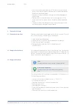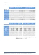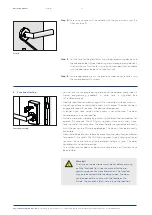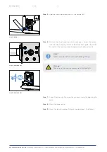
Step 9 (Illustration A)
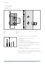
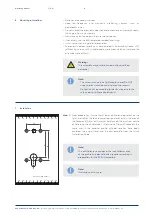
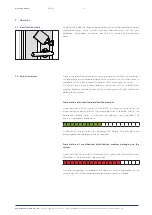
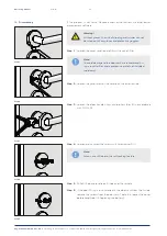
Step 9 (Illustration B)
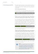
Step 7
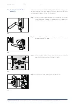
Step 8
Aug. Winkhaus GmbH & Co. KG
∙ Hessenweg 9 ∙ 48157 Münster ∙ T +49 251 4908 - 0 ∙ [email protected] ∙ www.winkhaus.de
ETB-IM
12
Operating manual
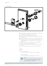
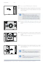
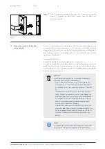
Step 7:
Take the base rosette for the B-side, push it around correctly (gap
for the cover rosette points downwards) on the spindle and guide it
through the drill holes in the door sash towards the door sash to the
stop. With a 8 mm and 9 mm spindle, guide the assembly assistance
included in the latch onto the spindle as shown, so that the flush-
mounting side points outwards and the gaps are pointing up and
down. Press the assembly assistance firmly into the base rosette.
Screw the base rosette with the door fitting with the M5 screws and
a screwdriver (PH2).
With 8 mm and 9 mm square pins, remove the assembly assistance
from the base rosette.
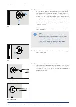
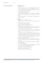
Step 8:
Press the cover rosette onto the base rosette until it engages
audibly and tangibly.
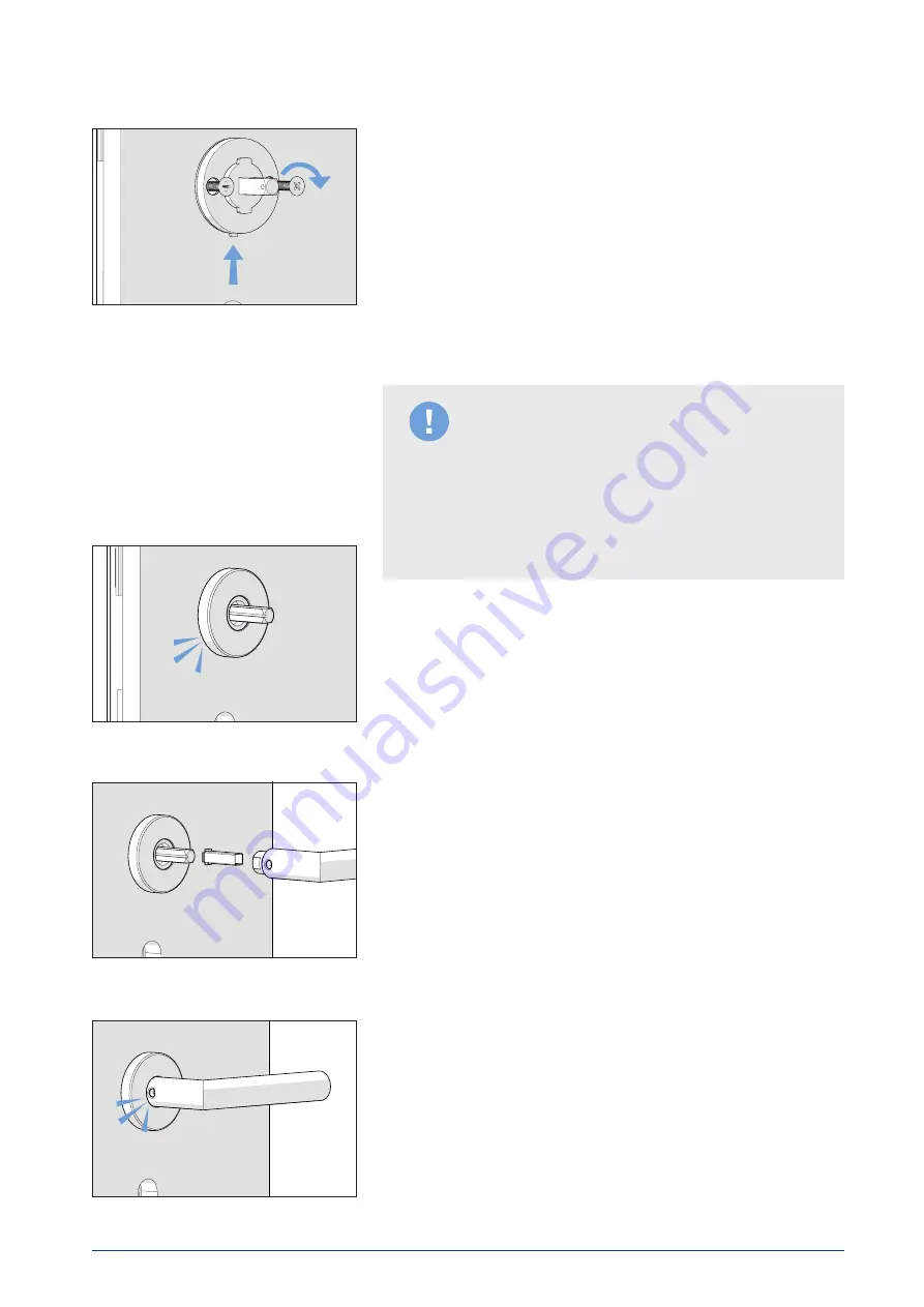
Step 9:
Take the handle for the B-side. With a 7 mm or 8.5 mm spindle,
insert the reducing sleeve provided into the door handle and push
it (with the optional sleeve) onto the spindle on the B-side
(Illustration A). Push on the handle until it engages audibly and
tangibly (Illustration B).
Note!
If profile cylinder rosettes have been ordered, use the
longer screws for the electronic door fitting. The screw
lock coating means that higher force is required to
screw in the screws. Do not overtighten the screws.
Ensure that the lock and the door sash do not brace
due to the screws being tightened too tightly.
Содержание blueSmart ETB-IM
Страница 1: ...Operating manual blueSmart electronic door handle for internal doors ETB IM...
Страница 29: ......


