background image

Step 3

Step 4

Step 5

Step 6

Aug. Winkhaus GmbH & Co. KG

 ∙ Hessenweg 9 ∙ 48157 Münster ∙ T +49  251  4908 - 0 ∙ [email protected] ∙ www.winkhaus.de

ETB-IM

11

Operating manual

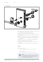
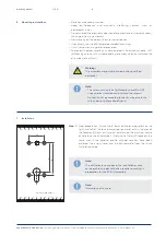
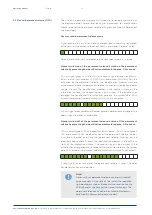
Step  2:  

Insert the lock and the profile cylinder in the door again. 

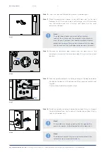
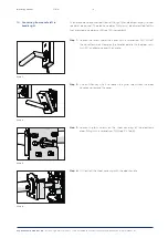
Step 3:   

Place the adjustment sleeves in the drill holes next to the lock 
follower. For Ø 10 mm drill holes use the large, with Ø 9 mm holes 
use the medium and with Ø  8  mm drill holes use the small 
adjustment sleeves.

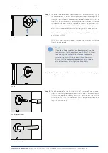
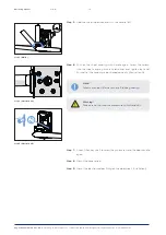
Step 4:   

Remove the electronic door handle from the box and turn the 
coupling on the rear of the electronic door fitting into the correct 
position.

Step 5:   

Take the spindle and push it into the coupling of the electronic door 
handle on the back until the pressure fitting engages audibly and 
tangibly.


Then remove the battery contact strips.

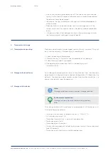
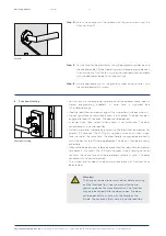
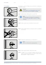
Step 6:   

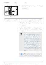
Feed the spindle, including the electronic door fitting, in through 
the lock follower from the A-side until the electronic door fitting is 
touching the door sash.

Note!

The adjustment sleeves are essential for rotation 
locking! Do not carry out the assembly without adjust-
ment sleeves! For doors that need an additional torsion 
protection the door fitting can be screwed with the door 
sash by means of the two upper holes beneath the cover.

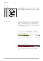
Note!

The spindle must be designed so that the gap for the 
grub screw points to the deadbolt and the door latch.

Note!

The electronic door fitting can only be mounted if the 
spindle has been measured correctly.

Содержание blueSmart ETB-IM

Страница 1: ...Operating manual blueSmart electronic door handle for internal doors ETB IM...

Страница 2: ...mart locking system 9 5 5 Dismantling the old door fitting 8 5 6 Dismantling the lock and door handle 9 6 Mounting instructions 10 7 Mounting 10 8 Functional testing 13 9 Operation 14 9 1 Identificati...

Страница 3: ...ganisation winkhaus de www winkhaus de ETB IM 3 Operating manual 1 Included in delivery Electronic door fitting A side Handle for B side Base rosette for B side 2x M5 screws for optional rosette pair...

Страница 4: ...ves each for hole diameters 8 9 and 10 mm for optimal positive screw connection of the electronic fitting rotation lock Optional 2 x M5 screws in a suitable length for the specified door thickness for...

Страница 5: ...as prevented access to injured or endangered persons and associated property damage and personal injury For securing doors the simultaneous use of a profile cylinder in the door lock is recommended to...

Страница 6: ...ately of any damage 3 Check to ensure supply is complete 4 Close packaging and leave contents in the packaging until installation or use For prolonged storage periods remove the batteries from the ele...

Страница 7: ...if the dimensions are suitable The following are also required for disassembling the existing door fitting see 14 Disassembly optionally available Cover lifter Art no 492 935 3 Circlip pliers form B i...

Страница 8: ...7 137 4 115 mm Art no 507 137 2 If the electronic door handle has to be mounted on a different door this is possible within tight tolerances with the screws and square pins provided If a conversion is...

Страница 9: ...d lock 2 must be removed from the door before drilling Note To avoid damage to the door sash we recommend us ing a rosette lifter and a protective plate not included in delivery 1 2 5 4 Integrating th...

Страница 10: ...profile cylinder hole often require reworking in preparation for the ETB IM assembly Note Illustration not to scale 7 Installation 6 Mounting instructions Batteries are already inserted Keep low frequ...

Страница 11: ...d push it into the coupling of the electronic door handle on the back until the pressure fitting engages audibly and tangibly Then remove the battery contact strips Step 6 Feed the spindle including t...

Страница 12: ...ette Screw the base rosette with the door fitting with the M5 screws and a screwdriver PH2 With 8 mm and 9 mm square pins remove the assembly assistance from the base rosette Step 8 Press the cover ro...

Страница 13: ...oor handle is engaged for about 3 seconds The door can be opened A longer signal tone sounds when access is not authorised The door handle remains in neutral position Activate permanent release by pre...

Страница 14: ...k and after the release position is reached not in the permanent release state The end of the release is not signalled The actuators noticeably move back Activation of the actuators for engaging the h...

Страница 15: ...surface The second signal is only output if the actuator has engaged the handle and the switch was noted in the system data With automatic permanent release switching this signal is not output 2 short...

Страница 16: ...ng to the specified values Manual override until the next switching via authorised identification medium regardless of the key time profile Auto ON Auto OFF manual intervention within time profile Per...

Страница 17: ...g threshold reached 3x 200 ms signal and red LED 200 ms pause 750 ms signal and red LED 200 ms pause Signal also with automatic permanent release switching The signal is generated if the discharged st...

Страница 18: ...14 Disassembly Step 1 Loosen the screw under the cover with a screwdriver PH1 Pull off the cover forwards towards the handle parallel to the door sash turn 90 and remove over the handle Step 2 Use an...

Страница 19: ...heet covering with handle again Screw the screws into the sheet covering with a screwdriver and tighten by hand Ensure that the coupling is positioned correctly Illustration A Step 7 Use an Allen key...

Страница 20: ...ischarge Replaced batteries must be recycled and must not be disposed of as household waste Observe the polarity of the batteries For safety reasons CE approval to achieve an optimal battery service l...

Страница 21: ...an angle and press on at the bottom Illustration B Step 9 Screw the cover to the carrier plate again with a screw Step 10 Carry out a battery replacement with the programming device Required for the...

Страница 22: ...the next contact to the locking system database via the blueControl software If an error occurs during the programming of the electronic door fitting it is usually caused by a transmission problem To...

Страница 23: ...lease position cannot be reached 10 x 50 ms signal and red LED 80 ms pause After a pause of approx 3 seconds a control impulse is generated again If this test is successful the process is complete Oth...

Страница 24: ...d and the door fitting is disengaged signal also with automatic permanent release switching If the status message Battery discharged is ignored by the user a 5 s continuous tone is output when the bat...

Страница 25: ...m B in accordance with DIN 5254 Step 4 Loosen and unscrew the screws with screwdriver PH 1 Step 5 Pull off the base rosette on B side over the spindle Step 6 If the door fitting is also screwed in the...

Страница 26: ...actuator and electronics without batteries can then be returned to disposal points for special electrical waste see below 15 Disposal instructions for product and packaging Disposal Environmental dam...

Страница 27: ...nsive permanent release modes Available in cover surface plastic black RAL 9005 deep black or white RAL 9003 signal white Stainless steel handle Different handle designs available With the relevant ha...

Страница 28: ...the Winkhaus virtual network Event memory last 2 000 locking events logging function can be deactivated if desired Battery warning message visual acoustic and optionally via the virtual network Intel...

Страница 29: ......

Страница 30: ...o KG Hessenweg 9 48157 M nster Germany T 49 251 4908 0 F 49 251 4908 145 winkhaus de zutrittsorganisation winkhaus de ZO MW November 2020 Print No 997 000 614 EN All rights including the right of alte...

Отзывы: