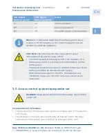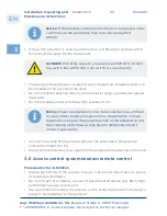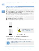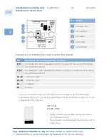
3
EN
Aug. Winkhaus GmbH & Co. KG
∙ Berkeser Straße 6 ∙ 98617 Meiningen
T +49 369 3950 - 0 ∙ www.winkhaus.de ∙ Subject to technical changes
blueMotion
5044745
42
Installation, Operating and
Maintenance Instructions
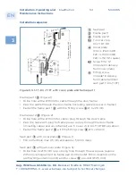
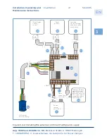
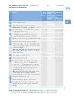
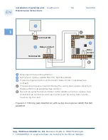
Figure 3.4-3: Installing
the external control unit
with battery and power
supply
Power supply
24 V / 2,5 A
Mains connection
230 V AC
Battery
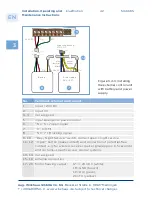
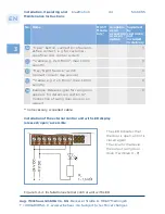
No.
Terminals external control unit
1
input + 24 V DC
2
input 0 V
3 - 4
not assigned
5
input emergency power control
6
"NC" 6 + 7 open signal
7
"C" (COM)
8
"NO" 7 + 8 locking signal
9 - 10
"Day / Night Service" switch, contact open = night service
11 - 12 "Open" button (make contact) and connection of potential-free
contact, e.g. for wireless receiver (pulse signal approx. 0.5 seconds)
and costumer-specific access control systems
13 - 14 not assigned
15 - 16 antenna connection
17 - 20 Motor housing output:
17 = + 24 V DC (white);
18 = GND (brown);
19 = RX (green);
20 = TX (yellow)
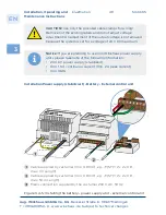
blue
brown/
black
PFS
green /
yellow
+ 24 V DC
0 V
+ 24 V DC
0 V
+ 24 V DC
0 V

