background image

3

EN

Aug. Winkhaus GmbH & Co. KG

 ∙ Berkeser Straße 6 ∙ 98617 Meiningen 

T +49  369  3950 - 0 ∙ www.winkhaus.de ∙ Subject to technical changes

blueMotion 

5044745

43

Installation, Operating and 
Maintenance Instructions

No. Name

MUST! 

Manda-

tory *

Available 

as on 

accessory 

or as on 

option

Supplied 

by 

customer/

not 

included 

in delivery

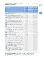
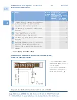
Power supply unit

X

Input emergency power control

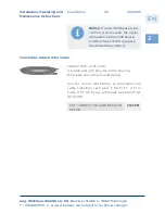
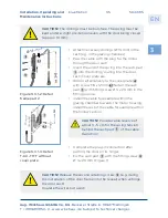
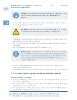
Notice!

 Without battery, connect to + 24 V!

** Cable (min. 4 x 0,8 mm

2

, max. 50 m 

Length) power supply

X

X

** Cable (min. 4 x 0,8 mm

2

, max. 1 m 

Length) emergency power supply

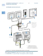
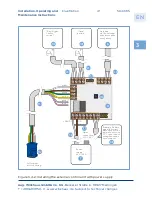
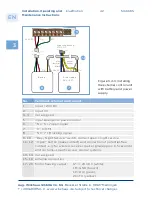
X

X

Battery, T-HT AKKU MIT LADESCHALTUNG

X

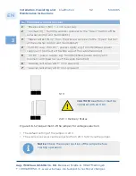
Antenna (mounting on the outside)

X

9.1

Antenna cable, custom-manufactured, 
2,5 m fixed to antenna, cable ends with 
wire end sleeve

Notice!


You may shorten the cable but 

not extend it!

 (longer cable, no warran-

ty for function)

Customer-specific ACS

X

External control unit

X

X

11.1

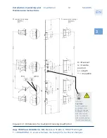
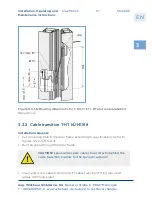
** Sash cable of the cable transition 
"T-KÜ-T1 FT ..." or "T-Connection 
cable 6 m ..." from the motor housing 
to the external control unit, cable ends 
with wire end sleeve or plug for the 
motor housing

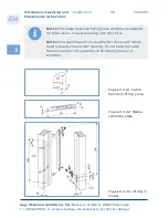
Notice!


Do not extend the cable! Grey 

and pink wire must be insulated!


(longer cable, no warranty for function)

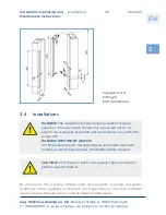
11.2

Plug for motor housing

11.3

Reset button of the error counter

11.4

Plug RS / LS optional for use as reset 
button of the error counter (parallel 
to 

11.3

)

Содержание blueMotion

Страница 1: ...winkhaus de blueMotion Motorised Multipoint Locking System 24 V DC Installation Operating and Maintenance Instructions 06 2018...

Страница 2: ...ond to the current status of this product s development and manufacture For the purpose of customer satisfaction and operational reliability of the blueMotion motorised multipoint locking system we re...

Страница 3: ...eep set single keeps p 19 Center keep FRA AV p 20 Magnetic bush p 20 Cable transition p 21 Cable transition sash part T K T1 FT p 21 Cable transition sash part T K T1 FT 2M 3 5 M p 21 Cable transition...

Страница 4: ...eless remote control set p 51 3 6 2 Wireless receiver separate p 53 3 7 Connection of swing door drive p 55 3 8 Non Winkhaus access control system ACS p 59 3 8 1 Non Winkhaus access control system ACS...

Страница 5: ...4 3 1 Operation p 78 4 3 2 Programming p 78 4 4 Wireless receiver for additional applications e g Garage door control units p 82 5 Maintenance and Care 6 Errors Causes Troubleshooting 7 Technical spe...

Страница 6: ...entire door furniture has been explicitly designed to be used in conjunction with genuine Winkhaus parts Other parts not recommended by Winkhaus may adversely effect the given properties of the motori...

Страница 7: ...in the event of malfunctions with profile cylinder in accordance with EN 1303 Corrosion Resistance Class 3 generally with cam position 30 in each case with smooth running free to turn function the use...

Страница 8: ...atch loads exceeding those of normal manual force are transmitted via the safety key onto the lock system perform a manual or mechanical locking or unlocking during the motor is working the handle is...

Страница 9: ...conjunction with genuine Winkhaus parts Using other parts may adversely effect the given properties of the security lock It must be ensured that the door can be closed without any problems by the key...

Страница 10: ...justment RS DIN right handed LS DIN left handed GR grey powder coated EST stainless steel MC surface mat chrome plated silver color WS white powder coated Antenna Antenna of transponder set Control Ex...

Страница 11: ...e Instructions 2 Product description blueMotion is a state of the art system to security lock entryway doors Easy to use and convenient All opening and closing members of the locking mecha nism are po...

Страница 12: ...g Winkhaus GmbH Co KG Berkeser Stra e 6 98617 Meiningen T 49 369 3950 0 www winkhaus de Subject to technical changes blueMotion 5044745 12 Installation Operating and Maintenance Instructions Figure 2...

Страница 13: ...nsition X Cable transition sash part T K T1 FT X Figure 2 1 T K T1 FT 2M 3 5M Cable Cable at the sash side 2 m or 3 5 m long plug for motor housing included Figure 2 2 Cable transition set T SET K T1...

Страница 14: ...HT BATTERY WITH CHARGING CONNECTION X Access control system shown antenna from the control unit transponder set Notice Only install the antenna from the transponder set in the external zone around th...

Страница 15: ...nges blueMotion 5044745 15 Installation Operating and Maintenance Instructions blueMotion is a fully motorized triple point lock including motor housing sensor can be used DIN right handed DIN left ha...

Страница 16: ...60 L03 80 92 10 M2 MC 5006975 T BM F2060 L13 45 92 8 M2 MC 5046015 T BM F2060 L13 50 92 8 M2 MC 5046016 T BM F2060 L13 55 92 8 M2 MC 4940335 T BM F2060 L13 55 92 10 M2 MC 4985948 T BM F2060 L13 55 92...

Страница 17: ...2228869 T BM U24185 L03 34 92 8 M2 MC 5026882 T BM U2460 L03 35 92 8 M2 MC 5046032 T BM U2460 L03 35 92 10 M2 MC 5046031 T BM U2460 L03 35 92 8 M2 GR 2130360 T BM U2460 L03 35 92 10 M2 EST 2195075 T...

Страница 18: ...9 F2060 L19 35S 92 9 M2 MC 5055868 T BM EN179 F2060 L19 65S 92 9 M2 MC 5045964 T BM EN179 F2069 L19 35S 92 9 M2 MC 5055869 T BM EN179 U2460 L36 35S 92 9 M2 MC 5045965 T BM EN179 U2460 L36 40S 92 9 M2...

Страница 19: ...separately The magnetic bush has to be installed in the frame and gives a signal to the reedsensor in motor housing Keep rail extension keep set single keeps Select the appropriate frame components k...

Страница 20: ...entrance doors Select the respective keeps according to the profile systems in the current program manual see program overview keep Chapter 2 Magnetic bush Magnetic bush adjustable color grey to trig...

Страница 21: ...with retaining screws 3 x 20 mm Sash part with spring sleeve in different versions see table order frame part separately see installed concealed in the airgap electric interface between sash and frame...

Страница 22: ...motor housing 3 for use with BM and fingerprint ekey home integra IDENCOM BioKey INSIDE as well as with other sash side access control systems sash part 1 5 m cable end of the cable with 5 pole plug...

Страница 23: ...4M 5040503 Frame part with 0 6 m cable and plug for frame power supply inclusive cover strip STV K T1 RT R8 to cover the profile hole on the frame side T K T1 RT KABEL 0 6M RNT 5040504 Cable transiti...

Страница 24: ...of a second blueMotion with the same power supply is not possible A separate power supply must be used for each lock If you do not use the Winkhaus power supply unit please keep in mind the following...

Страница 25: ...Instructions Frame power supply optional The Winkhaus frame power supply is a switching power supply single phase primary pulsed ins tallation current supply high pulse load capacity short circuit pr...

Страница 26: ...ined state of system in the event of a power outage it is not on alternative means of power supply for continuous operation It is mandatory to replace the battery approx every 3 years or 1 000 chargin...

Страница 27: ...l set T CONTROL WIRELESS REMOTE CONTROL SET F02 2126977 Access control systems From the outside the door is opened via the access control system transponder wireless remote control or a non Winkhaus a...

Страница 28: ...R12 External control unit in the housing for plug in wiring for sash side access control systems e g Fingerprint ekey Idencom Sommer in the door sash Housing for mounting the external control in the...

Страница 29: ...ww winkhaus de Subject to technical changes blueMotion 5044745 29 Installation Operating and Maintenance Instructions Cable 6 m 5 x 0 25 mm2 1st cable end with plug for motor housing 2nd cable end wit...

Страница 30: ...h smooth running free to turn function the use of a FZG cylinder is recommended DANGER With panicLock blueMotion BM a rechargeable battery with charging connection item no 2121455 is to be installed 3...

Страница 31: ...function 3 EN Aug Winkhaus GmbH Co KG Berkeser Stra e 6 98617 Meiningen T 49 369 3950 0 www winkhaus de Subject to technical changes blueMotion 5044745 31 Installation Operating and Maintenance Instr...

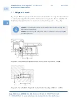
Страница 32: ...al changes blueMotion 5044745 32 Installation Operating and Maintenance Instructions By means of the magnetic bush and sensor in the motor housing the door status is checked open closed and the motori...

Страница 33: ...structions Figure 3 2 2 Magnetic bush adjustments You can adjust the mag net with a screw driver by 3 mm on two planes After installing the door you will have to adjust the magnet in such a way as to...

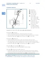
Страница 34: ...use T Cover strip K T1 RT R8 einsetzen Fasten the frame part 2 with the fitting screw 3 x 20 mm Installation sequence Sash part Frame part 1 Frame part 2 T Cover strip K T1 RT R8 Cover plate F16 L 12...

Страница 35: ...g and Maintenance Instructions Attach necessary drillings 13 mm in the sash e g in the glazing chamber Pass the cable with the plug for the motor through the door sash Insert the end of the spring int...

Страница 36: ...24 V DC yes brown 0 V ground yes green data bus RS 232 yes yellow data bus RS 232 yes grey Free CAUTION Motor housing is connected to ground brown Insulate unused wires no pink Free CAUTION Motor hous...

Страница 37: ...ion 5044745 37 Installation Operating and Maintenance Instructions Figure 3 3 1 6 Routing dimensions for T K T1 FT RT and cover plate F24 in aluminum 3 3 2 Cable transition T HT K M1188 Installation s...

Страница 38: ...18 mm fixed pivotal point and 180 opening Do not bend the cable transition and do not undershoot the bending radius of 25 mm 3 EN Aug Winkhaus GmbH Co KG Berkeser Stra e 6 98617 Meiningen T 49 369 395...

Страница 39: ...bund im Schlie zylinder stecken CAUTION First the door has to close easily then you can test electrical performance 3 EN Aug Winkhaus GmbH Co KG Berkeser Stra e 6 98617 Meiningen T 49 369 3950 0 www w...

Страница 40: ...f swing door drive or on request 3 EN Aug Winkhaus GmbH Co KG Berkeser Stra e 6 98617 Meiningen T 49 369 3950 0 www winkhaus de Subject to technical changes blueMotion 5044745 40 Installation Operatin...

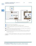
Страница 41: ...3 4 2 Installing the external control unit with power supply Antenna In the external zone around the entry door Open button Day Night Service switch to from the motor housing white brown green yellow...

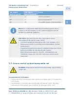
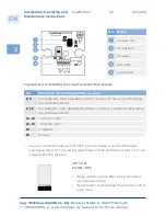
Страница 42: ...ol unit 1 input 24 V DC 2 input 0 V 3 4 not assigned 5 input emergency power control 6 NC 6 7 open signal 7 C COM 8 NO 7 8 locking signal 9 10 Day Night Service switch contact open night service 11 12...

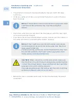
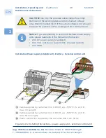
Страница 43: ...MIT LADESCHALTUNG X Antenna mounting on the outside X 9 1 Antenna cable custom manufactured 2 5 m fixed to antenna cable ends with wire end sleeve Notice You may shorten the cable but not extend it lo...

Страница 44: ...ic access control system X Cable e g 2 x 0 8 mm max 100 m Length X Day Night Service switch contact closed day service X Cable e g 2 x 0 8 mm2 max 100 m Length X Example Release signal for swing door...

Страница 45: ...to technical changes blueMotion 5044745 45 Installation Operating and Maintenance Instructions Installation of external control unit with acoustic signal indicating free open accessible The buzzer ind...

Страница 46: ...e used at the same time they must be switched parallel to the Open button e g button from inside wireless remote and intercom 3 EN Aug Winkhaus GmbH Co KG Berkeser Stra e 6 98617 Meiningen T 49 369 39...

Страница 47: ...stallation Operating and Maintenance Instructions After eliminating the error cause the electrically locking can be reset To do this please press the reset button of the error counter on the external...

Страница 48: ...N Aug Winkhaus GmbH Co KG Berkeser Stra e 6 98617 Meiningen T 49 369 3950 0 www winkhaus de Subject to technical changes blueMotion 5044745 48 Installation Operating and Maintenance Instructions Insta...

Страница 49: ...ure reliable troublefree operation DANGER Generally assemble and install always only with the power off 3 EN Aug Winkhaus GmbH Co KG Berkeser Stra e 6 98617 Meiningen T 49 369 3950 0 www winkhaus de S...

Страница 50: ...is used beside the door will have to provide a switch box with a filler panel for the control unit The transponder antenna is located in a box in exposed installation and is to be installed at the out...

Страница 51: ...erating and Maintenance Instructions 3 6 1 Wireless remote control set Installation sequence The wireless receiver should preferably be installed in a 65 mm deep switch box on the inside Unless use a...

Страница 52: ...eiver to the Open button of the external control unit terminal 11 3 Make contact NO from the wireless receiver to the Open button of the external control unit terminal 12 4 12 V DC resp 24 V DC power...

Страница 53: ...less receiver separate Separate wireless receiver for additional applications such as garage door con trol units Installation sequence Remove the housing cover Fasten the housing with screws Push in t...

Страница 54: ...ontact is open it closes by activating per remote control 9 10 NC relay K4 non operated contact is closed it opens by activating per remote control 11 12 12 V AC DC 11 13 24 V AC DC 14 Antenna 15 Scre...

Страница 55: ...tion Operating and Maintenance Instructions Relay becomes briefly active after being activated per remote control and after about 1 sec it will be deactivated automatically JP1 OFF K4 Impuls Figure 3...

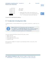
Страница 56: ...se button ACS motion detector etc potential free contact The opening impulse is transmitted by the swing door opener directly to the blueMotion via potential free contact Decontrol signal from blue mo...

Страница 57: ...igure 3 7 2 Wiring plan blueMotion with swing door opener and transponder set NC C NO Relay contact Relay contact Terminal X3 Relay contact gn 14 5 6 7 15 16 17 18 19 Terminal X6 230 V AC External con...

Страница 58: ...The signal continues until the swing door opener return to the close position 3 EN Aug Winkhaus GmbH Co KG Berkeser Stra e 6 98617 Meiningen T 49 369 3950 0 www winkhaus de Subject to technical change...

Страница 59: ...onal access controls and opening signals potential free signal e g Open button intercom If the blueMotion multipoint lock is used for others as the aforementioned sys tems such as transponder set remo...

Страница 60: ...BM including motor housing Art No on request 5 8 ekey article in PACKAGE 101940 5 ekey WH Adapter micro WH BM EAV 0 3 m Connection from control unit ekey home SE micro to the WH exter nal control uni...

Страница 61: ...on request 4 Frame power supply T NETZTEILRAHM 24 V DC 1 A 2 A 2 S Art No 5038589 5 8 ekey Article in PACKAGE 101940 5 ekey WH Adapter micro WH BM EAV 0 3 m Connection from control unit ekey home SE m...

Страница 62: ...dius 20 mm 101945 for aluminum and PVC square 24 mm 101948 5 ekey KAB BM 0 3 m 4 x 0 25 CP PAP4 WHS BMO Connection from ekey home SE micro plus to the WH external control unit 6 Fingerprint ekey FS AR...

Страница 63: ...NETZTEILRAHM 24 V DC 1 A 2 A 2 S Art No 5038589 5 8 ekey Article in PACKAGE for timber doors radius 20 mm 101945 for aluminum and PVC square 24 mm 101948 5 ekey KAB BM 0 3 m 4 x 0 25 CP PAP4 WHS BMO...

Страница 64: ...nit sash side 1 green yellow input for external potential free contact e g unlocking via inter com open button grey with battery pack on terminal PFS without battery pack together with white on 24 V D...

Страница 65: ...T NETZTEILRAHM 24 V DC 1 A 2 A 2 S Art No 5038589 4 230 V AC Description 5 7 ekey Article in PACKAGE for timber doors radius 20 mm 101941 for aluminum and PVC square 24 mm 101942 5 Fingerprint ekey ho...

Страница 66: ...unit sash side 1 Description 5 7 ekey Article in PACKAGE for timber doors radius 20 mm 101946 for aluminum and PVC square 24 mm 101947 5 Fingerprint ekey FS AR ED V SV 52 x 52 6 Control unit ekey hom...

Страница 67: ...T NETZTEILRAHM 24 V DC 1 A 2 A 2 S Art No 5038589 4 230 V AC Description 5 7 ekey Article in PACKAGE for timber doors radius 20 mm 101946 for aluminum and PVC square 24 mm 101947 5 Fingerprint ekey FS...

Страница 68: ...nal power supply top hat mounting rail Art No 5040503 3 T BM including motor housing Art No on request 5 Fingerprint unit IDENCOM suitable for Winkhaus blueMotion with integ rated cable plug in IDENCO...

Страница 69: ...Cable transition frame part T K T1 RT KABEL 0 6M RNT for fra me power supply Art No 5040504 3 T BM including motor housing Art No on request 4 Frame power supply T NETZTEILRAHM 24 V DC 1 A 2 A 2 S Art...

Страница 70: ...me part Cable transition T K T1 RT Cable 4M for external power supply top hat mounting rail Art No 5040503 3 T BM including motor housing Artikel No on request Figure 3 8 2 11 Wiring blueMotion withou...

Страница 71: ...n without external access control system with frame power supply sash side Description 1 Set of cable transition T SET K T1 FT INTEG BM 3 5 1 5 M EST including housing EV G cover plate depends on the...

Страница 72: ...alarm system takes place via the second relay of the integra 2 To this is a second cable transition needed e g T K T1 FT 2M Art No 5040501 This one to cut to length and connect the two red wires poten...

Страница 73: ...will have locked the door and will return to its initial position After proper locking an acoustic signal is given 4 1 blueMotion Should there be no or another acoustic signal please refer to chapter...

Страница 74: ...The door is unlocked from the outside via the connected access control e g transponder wireless remote control and the key Opening the door from the inside via the button via the intercom floating con...

Страница 75: ...via the antenna An acoustic door signal will acknowledge the data transfer The control checks whether this transponder chip is authorized to access and okays denies access 4 2 blueMotion with transpo...

Страница 76: ...amming card transponders programming card green delete all card red 4 2 2 Programming Teach in mode Programming card Set teach in mode Teach transponder Action Acoustic signal Result Pass the programm...

Страница 77: ...ION By using the delete all card all transponders stored in the system will be deleted The action of deleting all transponders is irrevocable once the process has been completed You have to teach up t...

Страница 78: ...ady been taught key A In order to trigger a signal press the A key of the taught in remote control The red LED will turn on and the door will be unlocked 4 3 blueMotion with wireless remote control 4...

Страница 79: ...nnn nnnn continuous signal is briefly interrupted pressed key s is are taught in If no remote control has been taught e g after delete all function it would apply to all remote control The teach in mo...

Страница 80: ...neously n short programming mode started 2 Press the A key of the same remote control nnnnnnnnnn continuous signal as long as delete mode is active programming mode active 3 Press keys A and B of a t...

Страница 81: ...s been filled to capacity max 85 keys if the teach in keys of a new wireless remote control is used and both LED displays of the receiver flash simultaneously Teaching wireless remote control directly...

Страница 82: ...lications you can program it as an ON OFF relay specified by the respective application Press and hold the P1 key of the receiver until the green LED lights up Release the key Press P1 again The LED f...

Страница 83: ...s out The desired key of the wireless remote control has been taught Teaching in via the wireless receiver item no 2142897 Partial deleting Press and hold the P1 key for about 2 seconds When the green...

Страница 84: ...the locking mechanism and smooth operation of the security lock at regular intervals at least once every three months At least once a year more frequently if under a higher stress factor all moveable...

Страница 85: ...l working properly e g opening locking mechanism is too stiff door can be warped door sash hanging improper installa tion check for proper door instal lation e g airgap re adjust the door e g re adjus...

Страница 86: ...st Additionally check keeps for damage check door settings keeps airgap adjust the keeps change the gaskit check the profile cylinder CAUTION Warning signal 10 x in sequence Blocking n 5 seconds long...

Страница 87: ...ugh in front of the antenna power outage bring the transponder chip closer approx 0 5 cm to the antenna hold the transponder chip in front of the antenna for a longer time Wireless receiver does not r...

Страница 88: ...ion top hat rail mounting 7 2 Frame power supply Input 230 V AC 47 63 Hz 0 6 A Output 24 V DC 1 A 2 A for 2 s Protection rating IP 20 Temperature range 10 C 55 C Earthing of the door frame Eyelet scre...

Страница 89: ...uperheterodyne Modulation AM ASK Frequency 433 92 MHz Number of code combiations 2 to the power of 64 as Rolling Code Frequency of the local oscillator 6 6128 MHz Intermediate frequency 10 7 MHz Sensi...

Страница 90: ...115 dB Input impedance 50 Ohm Max memory capacity 85 codes for the remote control Power supply unit 12 24 V AC DC Closed circuit current 15 mA On load current 33 48 mA Number of relays 1 NO NC Power...

Страница 91: ...BioKey INSI DE as well as with external access control system sash side Cross section 6 x 0 25 mm2 Sash part K T1 EV G FL GELTEIL 1 5 M Sash part with cable 1 5 m 6 x 0 25 mm cable ends with 5 pole p...

Страница 92: ...RANSITION H4 M1210 2126951 Cable transition adapter for cable transition T HT K M1188 e g for timber doors to co ver the fitting contour T HT WIRELESS REMOTE CONTROL F01 ANTHRAZIT 2126782 2 channel re...

Страница 93: ...tion emergency exit locking system to EN 179 Appendix 2 Classification emergency exit locking system to EN 179 Maximum door sash height 2500 mm Maximum door sash width 1500 mm Article no Backset Centr...

Страница 94: ...ecified by the manufacturer c An emergency power back up must ensure that the bolt always reaches the end position in the event of a power failure Article no VS type Func tion Backset Centre distance...

Страница 95: ...r systems for the evaluation and inspection of the performance reliability of the construction product in accordance with Annex V of the Construction Products Regulation CPR System 1 7 The MPA NRW wit...

Страница 96: ...with Article 12 paragraph 2 CPR N A 6 Systems or systems for the evaluation and inspection of the performance reliability of the construction product in accordance with Annex V of the Construction Pr...

Страница 97: ...rticle 12 paragraph 2 CPR N A 6 Systems or systems for the evaluation and inspection of the performance reliability of the construction product in accordance with Annex V of the Construction Products...

Страница 98: ...ug Winkhaus GmbH Co KG Berkeser Stra e 6 D 98617 Meiningen T 49 3693 950 0 F 49 3693 950 134 winkhaus de tuerverriegelung winkhaus de T SB June 2018 Print No 5044745 EN All rights and changes reserved...

Отзывы: