


26
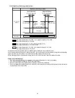
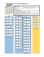
10. Flow diagram for the programming levels
PV/SV display mode
PV
A1 value
A1 value is
displayed.
PV
A2 value
A2 value is
displayed.
PV
A3 value
A3 value is
displayed.
Alarm setting mode
A1 value
A2 value
A3 value
Returns to PV/SV display
mode.
Auxiliary function setting mode 2
Input type
Scaling high
limit
Scaling low
limit
Decimal
point place
PV filter time
constant
A1 type
A2 type
A3 type
A1 Energized /
De-energized
A2 Energized /
De-energized
A3 Energized /
De-energized
A1
hysteresis
A2 hysteresis
A3 hysteresis
A1 delay
time
A2 delay
time
A3 delay
time
Transmission
output 1 high
limit
Transmission
output 1 low
limit
Event input
function
A1 HOLD
function
A2 HOLD
function
A3 HOLD
function
Square root
function
Low level
cutoff
Returns to PV/SV display mode.
Maintenance mode
A1 output
ON/OFF
A2 output
ON/OFF
A3 output
ON/OFF
Trans.
output 1
manual
output
Returns to PV/SV display
mode.
Auxiliary function setting mode 1
Set value lock
Sensor
correction
coefficient
Sensor
correction
Returns to PV/SV display
mode.
+
+
(3 sec)
+
(5 sec)
Power ON
+
+
+
[About setting item]
•
Upper left: PV Display: Indicates the setting item characters.
•
Lower left: SV Display: Indicates the factory default. Right side: Setting item
•
: Available only when option is ordered.
[About key operation]
•
+
: Press the
and
key (in that order) together. The unit will move to the next setting
item, illustrated by an arrow.
•
: Press the
key. The unit will move to Alarm setting mode.
•
+
(3 sec): Press and hold the
and
key (in that order) together for approx. 3 sec. The
unit will move to Auxilary function setting mode 1.
•
+
+
(3 sec): Press and hold the
,
and
keys (in that order) together for
approx.3 sec. The unit will move to Auxiliary function setting mode 2.
•
+
(5 sec): Press and hold the
and
keys (in that order) together for approx. 5 sec. The
unit will move to Maintenance mode.
A1 value
+
(3 sec)
Содержание DI25
Страница 1: ...DIGITAL INDICATOR DI25 Operating instructions ...
Страница 28: ...28 14076218 02 05 2018 EN ...