


10
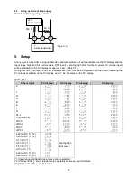
4.3
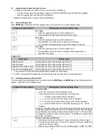
Using as a crrent loop supply
Refer to the following wiring example.
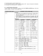
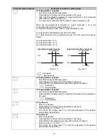
5. Setup
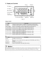
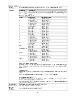
After power is turned ON, the input characters and temperature unit will be indicated on the PV display, and the
input range high limit (for thermocouple, RTD input) or scaling high limit (for direct current, DC voltage input)
will be indicated on the SV display for approx. 3 sec. (Table 5-1).
During this time, all outputs and LED indicators are in an OFF status. Operation will then start, indicating the
PV (process variable) on the PV display, and A1, A2, A3 value on the SV display.
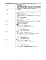
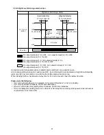
(Table 5-1)
Sensor input
PV display ( )
SV display
PV display ( )
SV display
K
J
R
S
B
E
T
N
PL-
C (W/Re5-26)
Pt100
JPt100
Pt100
JPt100
4-20 mA DC (*1)(*2)
0-20 mA DC (*1)(*2)
0-1 V DC (*1)
0-5 V DC (*1)
1-5 V DC (*1)
0-10 V DC (*1)
4-20 mA DC (*1)(*3)
0-20 mA DC (*1)(*3)
Scaling high
limit value
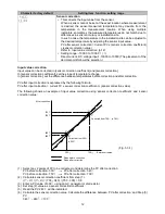
(*1) Input range and decimal point place can be selected.
(*2) Connect a 50 shunt resistor (sold separately) between input terminals.
(*3) Has a built-in 50 shunt resistor.
(Fig. 4.3-1)
24 V
power circuit
20
19
18
+
-
2-wire transmitter
+
-
+
50
250
Содержание DI25
Страница 1: ...DIGITAL INDICATOR DI25 Operating instructions ...
Страница 28: ...28 14076218 02 05 2018 EN ...


