


24
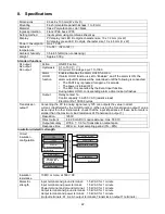
Power failure
countermeasure
The setting data is backed up in the non-volatile IC memory.
Self-diagnosis
The CPU is monitored by a watchdog timer, and if an abnormal status is found on the
CPU, the DI25 is switched to warm-up status.
Automatic cold
junction temp.
compensation
This detects the temperature at the connecting terminal between the thermocouple and the
instrument, and always maintains it at the same status as if the reference junction location
temperature was at 0 (32 ).
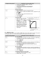
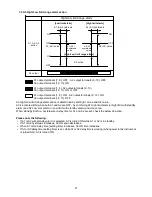
Event input
function
Selects event input function from 3 types of HOLD function and 2 types of alarm HOLD
function.
For further specifications see WIKA data sheet AC 80.02.
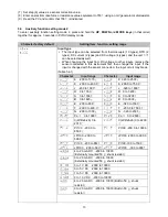
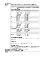
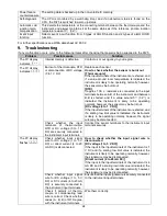
9. Troubleshooting
If any malfunction occurs, refer to the following items after checking that power is being supplied to the DI25.
Problem
Possible cause
Solution
The PV display
indicates
.
Internal memory is defective.
Contact us or our agency in your region.
The PV display
indicates
.
Burnout of thermocouple, RTD
or disconnection of DC voltage
(0 to 1 V DC)
Replace each sensor.
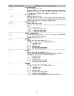
How to check whether the sensor is burnt out
[Thermocouple]
If the input terminals of the instrument are shorted, and
if a value around room temperature is indicated, the
instrument is likely to be operating normally, however,
the sensor may be burnt out.
[RTD]
If approx. 100 resistance is connected to the input
terminals between A-B of the instrument and between
B-B is shorted, and if a value around 0 (32 ) is
indicated, the instrument is likely to be operating
normally, however, the sensor may be burnt out.
[DC voltage (0 to 1 V DC)]
If the input terminals of the instrument are shorted, and
if a scaling low limit value is indicated, the instrument
is likely to be operating normally, however, the signal
wire may be disconnected.
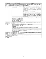
Check whether the input
terminals of thermocouple,
RTD or DC voltage (0 to 1 V
DC) are securely connected to
the instrument input terminals.
Connect the sensor terminals to the instrument input
terminals securely.
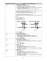
The PV display
flashes
.
Check whether input signal
wire for DC voltage (1 to 5 V
DC) or direct current (4 to 20
mA DC) is disconnected.
How to check whether the input signal wire is
disconnected
[DC voltage (1 to 5 V DC)]
If the input to the input terminals of the instrument is 1
V DC and if a scaling low limit value is indicated, the
instrument is likely to be operating normally, however,
the signal wire may be disconnected.
[Direct current (4 to 20 mA DC)]
If the input to the input terminals of the instrument is 4
mA DC and if a scaling low limit value is indicated, the
instrument is likely to be operating normally, however,
the signal wire may be disconnected.
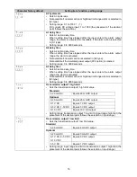
Check whether input signal
wire for DC voltage (1 to 5 V
DC) or DC current (4 to 20 mA
DC) is securely connected to
the instrument input terminals.
Ensure that the input signal wire is securely connected
to the instrument input terminals.
Check if polarity of thermo-
couple or compensating lead
wire is correct. Check whether
codes (A, B, B) of RTD agree
with the instrument terminals.
Wire them correctly.
Содержание DI25
Страница 1: ...DIGITAL INDICATOR DI25 Operating instructions ...
Страница 28: ...28 14076218 02 05 2018 EN ...