


11
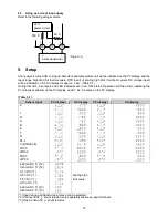
5.1
Registering the selected item or value
• To increase or decrease the numeric value, use the UP or DOWN key.
o
To make the set value change faster, press and hold the UP/DOWN key and FAST key together.
o
Select an
setting item with the UP or DOWN key.
• Register the setting item or value using the MODE key.
5.2
Alarm setting mode
If the
MODE key
is pressed in PV/SV display mode, the unit will move to alarm setting mode.
Character factory default
Setting item, function, setting range
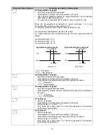
A1 value
• Sets A1 output action point, refer to (table 5.2-1).
• Not available if no alarm action is selected in [A1 type]
A2 value
• Sets A2 output action point, refer to (table 5.2-1).
• Not available if no alarm action is selected in [A2 type]
• Not available if insulated power output (P24 option) is ordered.
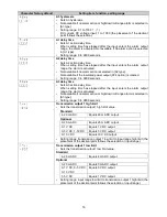
A3 value
• Sets A3 output action point, refer to (table 5.2-1).
• Not available if no alarm action or High/Low limit range alarm is
selected in [A3 type]
(Table 5.2-1)
Alarm type
Setting range
High limit alarm
Input range low limit to input range high limit (*1)
Low limit alarm
Input range low limit to input range high limit (*1)
High limit with standby alarm
Input range low limit to input range high limit (*1)
Low limit with standby alarm
Input range low limit to input range high limit (*1)
• The placement of the decimal point follows the selection or input range.
(*1) For DC current and DC voltage input: setting range is [scaling low limit to scaling high limit].
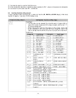
5.3
Auxiliary function setting mode 1
To enter auxiliary function setting mode 1, press and hold the
DOWN key
and
MODE key
(in that order) together for
approx. 3 seconds in PV/SV display mode.
Character factory default
Setting item, function, setting range
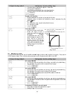
Set value lock
• Locks the set values to prevent setting errors.
• The setting item to be locked depends on the selection.
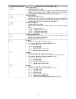
•
(Unlock): All set values can be changed.
(Lock 1): None of the set values can be changed.
(Lock 2): Only alarm setting mode (p.11) can be changed.
(Lock 3): All set values – except the input type (p.14) – can be
changed.
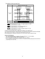
However, changed values revert to their previous value after power is turned
off because they are not saved in the non-volatile IC memory. Do not change
any setting items in auxiliary function setting mode 2 (pp.11 - 18). If any item
is changed in auxiliary function setting mode 2, it will affect the alarm value
(A1 value – A3 value).
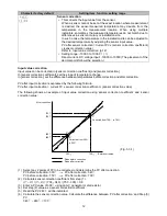
Sensor correction coefficient
• Sets sensor correction coefficient = slope of input value from a sensor.
• PV after sensor correction= Current PV x (sensor correction coefficient)
+ (sensor correction value)
Refer to input value correction’ (p. 12), Setting range: -10.000 to 10.000
Содержание DI25
Страница 1: ...DIGITAL INDICATOR DI25 Operating instructions ...
Страница 28: ...28 14076218 02 05 2018 EN ...


