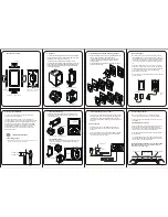


XTouch50 - Overview
Speaker
LAN + Power
over Ethernet
DC Power
Input
Microphone
Capvite
Screw
USB Reset
Switch
US 1 gang bracket
US 1 gang box
EU 1 gang box
UK 1 gang box
The XTouch50 has been designed to mount to a US standard
single gang junction box, low voltage bracket, EU single gang
junction box,
or UK single gang junction box.
– The XTouch50 mounting bracket, included in the box,
should be attached to the US single gang bracket/ US junction
box with the screws supplied. The XTouch50 attaches to the
included bracket via 2 captive screws located at the top and
bottom of the XTouch50.
b. Rough-In
e. Installing the XTouch50 mounting bracket
– Using the included screws mount the mounting bracket onto
the US 1 gang junction box, low voltage bracket.
– To install on EU/ UK 1 gang junction box, loosen out the
screws on the gang box first, then install and rotate the
mounting bracket.
– Verify that the bracket is level before tightening the captive
screws on the XTouch50.
Back of XTouch50
Front of XTouch50
Line in wall
24 DC
2Pin
24v Power Supply
– By utilizing a 24v power supply (not included) to power
the
XTouch50
you may provide power locally or remotely.
If powering locally be sure to run the wire through the wall
in accordance with local codes. If powering remotely be
sure to use wire of adequate gauge for the length of the
run.
– Verify the polarity of the 2 Pin connector on your power
supply prior to connecting to the
XTouch50
. The right pin
of the
XTouch50
Power Connector is positive and the left
pin is negative. If the wire is to be extended ensure
compliance with local codes.
– Plug the connector into the
XTouch50
DC jack on the back
of the
XTouch50
.
165 cm / 65”
145 cm / 57”
1
Installing the XTouch50
a. Mounting height
Planning the installation
The XTouch50 is designed to be wall mounted in either
Portrait or Landscape orientation.
The XTouch50 requires a minimum mounting depth of
1”(2.45cm) from the front surface plus room for cable/s. Power
may be supplied by Power Over Ethernet (PoE) or by a 24v
DC power supply (not included). PoE must meet the IEEE
802.3af standard. Direct power via a 24v DC external power
supply requires a minimum current output of 0.5A. The
XTouch50 connects to the local network via a hard wired
Ethernet connection.
– The recommend mounting height for the XTouch50 is 57”- 65”
(145 cm -165 cm) above the finished floor.
– Install the 1 gang box junction box or low-voltage bracket
in it’s normal orientation - with mounting screw holes at
the top and bottom.
XTouch50
XTouch50
c. Landsacpe Mounting
d. Portrait Mounting
– Install the single gang junction box or low-voltage bracket
horizontally - with
XTouch50
mounting screw holes on the
left and right sides.
EU 1 gang box
UK 1 gang box
US 1 gang bracket
US 1 gang bracket
EU 1 gang box
UK 1 gang box
Network Switch
PoE Injector
PoE Network Switch
To XTouch50
f. Connecting the XTouch to power
PoE Connection
– The XTouch50 is designed to be powered over the Ethernet
connection (PoE) or by connecting a 24v power supply (not
included), but not both. If both the PoE and a 24v power
supply are connected the
XTouch50
will draw power from the
24v source.
– PoE connection requires that IEEE 802.3af standard.
Utilize a network switch or PoE injector that meets this
standard.
– Connect the
XTouch50
using a standard T568A or T568B
Ethernet cable from the network switch to the LAN/PoE
jack on the back of the
XTouch50
.
XTouch50 Frame
T
op of 1 Gang Box
Mounting Bracket
Mounting Bracket
Dry Wall
g. Connecting Ethernet
h. Installing the XTouch50
– When not utilizing PoE, it is recommended that you
connect the XTouch50 directly to the network switch.
– Utilizing a T568A or T568B network cable connect to the
LAN/PoE jack.
– The XTouch50 snaps in when it’s pushed to the mounting
bracket, and will be held into the mounting bracket by 2
mounting screws which locate on the left and right sides of
the XTouch50 when mounted in landscape mode.
– Orient the XTouch50 for the desired portrait or landscape
mounting option.
– To complete the installation, insert the XTouch50 into the
included bracket and tighten the 2 captive screws to secure
the XTouch50 on the mounting bracket.
CAUTION: DO NOT PRESS DIRECTLY ON THE SCREEN
when installing the unit on to the mounting bracket.
Press only on the frame edges.


