manualshive.com logo in svg
background image

Panel Replacement Procedure

TH-37PX50U

TH-42PD50U

TH-42PX50U

Содержание TH-42PX50U

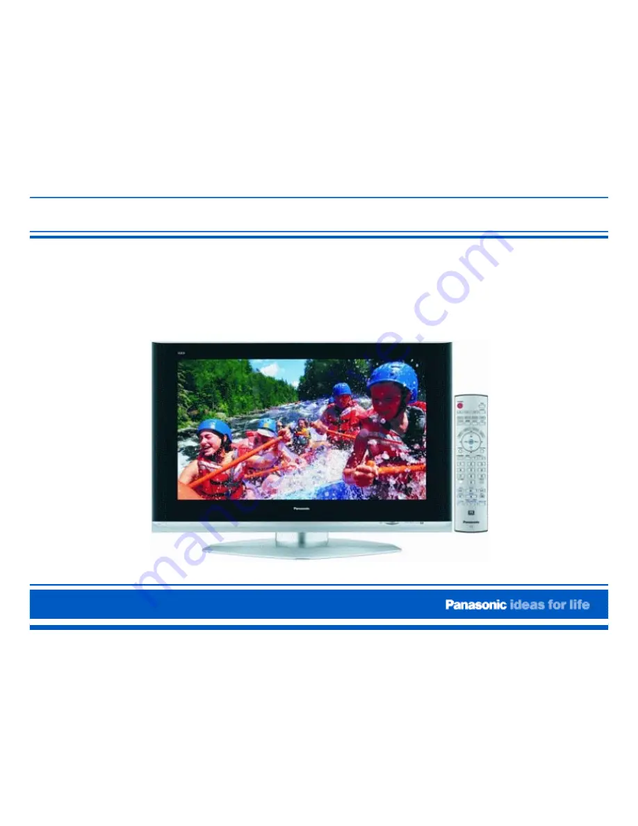
Страница 1: ...Panel Replacement Procedure TH 37PX50U TH 42PD50U TH 42PX50U...

Страница 2: ...he Technical Hotline Select the Settings and Connections by deleting those conditions that do not apply to the symptom picture 10 Picture Mode If the defect does not appear in all picture modes the pa...

Страница 3: ...r is complete and the defective panel shipped complete the remainder of the report by entering the Date Completed 29 Review the report for completeness Then email the report to the appropriate address...

Страница 4: ...l number of the unit must be attached here or attached to the email with the report The unit serial number must be legible A picture of the symptom as it appears in normal operation mode must be attac...

Страница 5: ...ective panel showing the following x The symptom x The serial number of the unit x The serial number of the defective panel x The red screen x The blue screen x The green screen 4 The servicer will co...

Страница 6: ...hem to excessive force When inserting a ribbon cable into a socket verify that the cable is straight Angled insertion can create an electrical short circuit and permanently damage the panel High Volta...

Страница 7: ...emove the four screws that secure the protective cardboard on the new panel Place the protective cardboard aside Figure 4a Figure 4b Unwrap the protective packaging from the new panel Important Note T...

Страница 8: ...ration of New Panel PCB Description Disassembly and Reassembly Procedure Lead Dressing Adjustment Driver Setup Procedure Adjustment White Balance of GP8DU Chassis Adjustment White Balance Procedure of...

Страница 9: ...tatic 5 foot by 4 foot foam cushioning Plasma Stand Part TY ST05K or equivalent Screw storage bin Large flat work area Colorimeter for white balance adjustment Sencore CP288 or equivalent Video Signal...

Страница 10: ...ht position Leads or Ribbon Cables No pulling no bending no excessive force Ribbon cables must be straight when inserted into sockets Angle insertion can create an electrical short circuit Anti static...

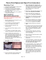
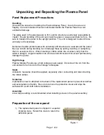
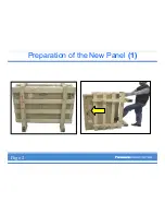
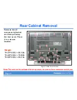
Страница 11: ...Preparation of the New Panel 1 Page 2...

Страница 12: ...the New Panel 2 Preparation of the new Panel 2 Caution Use extreme care when handling the Plasma Display Panel The glass used in the plasma panel is thin and its structure is extremely susceptible to...

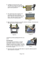
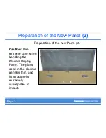
Страница 13: ...Preparation of the New Panel 3 Page 3...

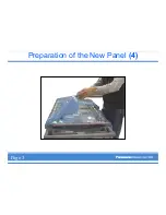
Страница 14: ...Preparation of the New Panel 4 Page 3...

Страница 15: ...icated and then pull away the rear cover Place it in a secure location Figure 7 Back Cover Screws Weight TH 37PX50U 66 14lb TH 42PX50U 76 06lb TH 50PX50U 99 21lb Note The unit can be awkward for one p...

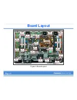
Страница 16: ...Board Layout Figure 8 Board Layout Page 4...

Страница 17: ...Removal of the fans Figure 9 Fans Location 1 Remove the three screws that secure each of the three fans 2 Place the fans in a secure location Page 5...

Страница 18: ...R and the black connector that couples the K board and the DG board 2 Disconnect the connectors DG3 and DG5 of the DG board PB7 of the PB board and PA10 of the PA board 3 Remove the five screws that h...

Страница 19: ...he P board 1 Unlock the cable clampers to free the cables 2 Disconnect the couplers P2 P5 P9 P10 P11 P12 P23 P25 and P30 from the P board 3 Remove the six screws as indicated in Figure 12 Figure 12 P...

Страница 20: ...5 from the D board The connectors D3 and D5 are already disconnected from the DG board 2 Remove the three screws as indicated in Figure 13 and remove the PB Board metal frame The PB board remains atta...

Страница 21: ...Removal of the D board 1 Disconnect the flexible cables D31 D32 D33 and D34 2 Remove the four screws of the D board as indicated in figure 14 and place the D board aside Figure 14 D Board Page 7...

Страница 22: ...sconnect the bridge connector SU45 or SC45 and slide the SU board to the left to disconnect the coupler SC41 SU41 from the SC board 3 Remove the flexible cables SU1 SU2 SU3 SU4 and place the SU board...

Страница 23: ...er insulator located underneath the SC board and transfer it to the new panel 2 Perform the same action for the rubber insulator located underneath the SS board 3 This done to prevent arcing the board...

Страница 24: ...18 SS2 and SS3 boards Figure 18B SS board connector 1 Disconnect the coupler SS23 from the SS2 board 2 Disconnect the flexible cable SS55 See figure 18 and 18B 3 Remove the two screws that secure the...

Страница 25: ...f the cable bracket 2 Unlock the sockets C11 and C21 to disconnect the two ribbon cables that attach the D board to the C1 and C2 boards 3 Install the flexible cables and bracket to the new panel 4 Re...

Страница 26: ...5 Removal of Front Escutcheon Remove the 8 screws as indicated in figure 25 Note The metal plate at the bottom left side of the picture automatically falls off when the screws are removed Place it asi...

Страница 27: ...and Brackets Figure 26 Right Stand Bracket CN S1 1 Remove the three screws of the right stand bracket as indicated in figure 26 2 Disconnect the connector S1 of the S board 3 Free the cable from the r...

Страница 28: ...the Front Cabinet Figure 28 Escutcheon Removal With the help of an assistant the Cabinet can now be removed from the panel by tilting the bottom out and lifting up slightly Place it in a secure locati...

Страница 29: ...9 Panel on Table With the help of an assistant remove the plasma panel from the servicing stand Lay it facing down on a flat surface such as a table covered with a cushioned anti static mat and a soft...

Страница 30: ...e plasma television from the stand The television should be placed face down on a table equipped with a cushioned anti static mat and a soft cloth 1 Remove the 4 screws securing the left stand bracket...

Страница 31: ...Lead Dressing Figure 39 Lead Dressing Location Page 20...

Страница 32: ...42PX50U Name Test point Voltage Volume Vsus TPVSUS SS BOARD 188V 2V VR351 P BOARD Ve TPVE SS BOARD 160V 1V VR6145 SS BOARD Vset TPVSET SC BOARD 240 V 7V Verify Only Vad TPVAD SC BOARD 105V 1V VR6477 S...

Страница 33: ...ut a Crosshatch signal Set the picture mode to Normal and White Balance to Normal Test point Volume Level Remark T1 TPSC1 SC 10 10 5 Sec TH 42PX50U 20 15 Sec TH 50PX50U T2 TPSC1 SC VR6557 SC 210 10 Se...

Страница 34: ...Drive Waveform Item Preparation Input a Crosshatch signal Set the picture mode to Normal and White Balance to Normal Figure 34 Initialization Waveform Page 25...

Страница 35: ...Control to display the Serviceman Adjustment Menu Press Power again on the Remote Control to exit the Serviceman Adjustment Menu Exiting the Serviceman Mode Press the Power button on the receiver Not...

Страница 36: ...ton on the remote To exit the CAT mode access the ID mode and switch off the main power INPUT CAT Panel sys 8 2 IIC Mode CD Mode SD Mode MS Mode ID Mode I2C Mode Select the I2C mode by pressing the Up...

Страница 37: ...ote control 2 Select the alignment item by pressing the number 4 button on the remote control 3 Adjust the optimum setting by pressing the Volume Up Down buttons on the remote control The data is memo...

Страница 38: ...I2C Mode Menu Structure B Page 32...

Страница 39: ...TSC White Balance Adjustment Color Temperature X Y Cool High 0 276 0 276 Normal Mid 0 288 0 296 Warm Low 0 313 0 329 20 IRE Window pattern 80 IRE Window pattern Table 9 Color Temperature Values Page 3...

Страница 40: ...PDP White Balance Adjustment INPUT Equipment required NTSC Pattern Generator Colorimeter Panel Settings Picture Standard Color Temperature Cool Aspect Ratio 16 9 Page 34...

Страница 41: ...e Balance Adjustment Step 1 Using the Pattern generator apply a 20 IRE Window pattern signal to the panel Apply the color sensor to the panel and monitor the values Color Sensor 20 IRE Window Pattern...

Страница 42: ...PDP White Balance Adjustment Step 2 Adjust the Sub Bright Setting to 10cd m2 Page 34...

Страница 43: ...PDP White Balance Adjustment Step 3 IIC Y525I JUST Mid Panel W B Adj G Cutoff 80 80 IIC Y525I JUST Mid Panel W B Adj G Cutoff 80 80 Before After Set the G Cutoff Setting Value to 80 Page 34...

Страница 44: ...e Balance Adjustment Step 4 1 Before IIC Y525I JUST Mid Panel W B Adj R Cutoff 88 88 IIC Y525I JUST Mid Panel W B Adj R Cutoff 88 7B After Adjust the Red Cutoff settings to match the values in Table 1...

Страница 45: ...hite Balance Adjustment Step 4 2 IIC Y525I JUST Mid Panel W B Adj B Cutoff 91 91 IIC Y525I JUST Mid Panel W B Adj B Cutoff 91 8F Before After Adjust the Blue Cutoff settings to match the values in Tab...

Страница 46: ...PDP White Balance Adjustment Step 5 Before IIC Y525I JUST Mid Sub adjust Sub bright 3D 3D IIC Y525I JUST Mid Sub adjust Sub bright 3D 3F After Readjust the Sub Bright setting to 10 cd m2 Page 34...

Страница 47: ...PDP White Balance Adjustment Step 6 Apply an 80 IRE window pattern signal to the Panel 80 IRE Window Pattern Page 34...

Страница 48: ...PDP White Balance Adjustment Step 7 IIC Y525I JUST Mid Panel W B Adj G Drive F3 E8 IIC Y525I JUST Mid Panel W B Adj G Drive F3 F3 Before After Set the G Drive Setting value to E8 Page 34...

Страница 49: ...te Balance Adjustment Step 8 1 IIC Y525I JUST Mid Panel W B Adj R Drive ED C6 IIC Y525I JUST Mid Panel W B Adj R Drive ED ED Before After Adjust the Red Drive settings to match the values in Table 1 P...

Страница 50: ...p 8 2 IIC Y525I JUST Mid Panel W B Adj B Drive FC E2 IIC Y525I JUST Mid Panel W B Adj B Drive FC FC Before After Adjust the Blue Drive settings to match the values in Table 1 Sencore isf is a trademar...

Страница 51: ...ly the 20 IRE pattern and 80 IRE patterns and verify that the drive and cutoff settings match the settings in Table 1 adjust as necessary Table 1 Color Temperature X Y Cool High 0 276 0 276 Normal Mid...

Страница 52: ...PDP White Balance Adjustment Step 10 Before Adjust the All Drive Settings value to FC IIC Y525I JUST Mid Panel W B Adj All Drive E2 FC IIC Y525I JUST Mid Panel W B Adj All Drive E2 E2 After Page 34...

Страница 53: ...justment Step 11 Reapply the 20 IRE pattern and verify the light settings match the table below adjust as necessary Table 1 Color Temperature X Y Cool High 0 276 0 276 Normal Mid 0 288 0 296 Warm Low...

Страница 54: ...or temperature to Normal Press the R button again then the Action button to re access the IIC mode Step 13 Repeat steps 2 to 11 for Normal Color Temperature Step 14 Press the R button then the Picture...

Страница 55: ...PDP White Balance Adjustment Step 16 Change the Color temperature to Cool Mode then re adjust the Sub bright value to 30 IIC Y525I JUST Mid Sub adjust Sub bright 3D 30 Sub Bright set to 30 Page 34...

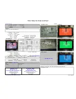
Страница 56: ...Examples Of Defective Panels Horizontal and Vertical error Page 37...

Страница 57: ...Examples Of Defective Panels 2 Errors Changing Not a Full Width Page 38...

Страница 58: ...Examples Of Defective Panels 3 Errors in 2 places Errors Changing Page 38...

Страница 59: ...Examples Of Defective Panels 4 These are NOT TH 42PW5UZ or TH 37PW5UZ Panels Double Width Error Page 39...

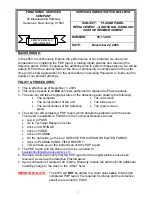
Страница 60: ...Panel Replacement Procedure...

Отзывы: