LEONARDO PRO X
User manual
EN
13
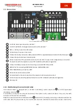
2.2.2.4. Inverter switch
There is no need for a DC isolating device, as this is already integrated into each battery.
The inverter is switched on when the switch is in position (I) and off when the switch is in
position (O)
The switch must not be set to position (II) for any reason.
Pic.12 - INVERTER switch
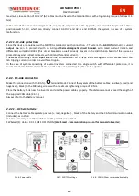
2.2.3. Current Sensor (TA) Installation
Install the supplied current sensor (if necessary, according to the installation diagram) following the connection
diagrams 1-2-3-4 and respecting the direction of the arrow:
the direction of the arrow in the diagram must be the
same as the direction shown on the sensor
.
Maximum length: 20 m
Fig. Cablaggio sensore di corrente
Pic.13 - Current sensor wiring
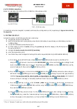
2.2.4. Control Meter P1 Installation - AC Configuration ONLY
Control Meter P1
provides a direct connection of the AC power cables of the existing PV system in order to read the PV
power produced.
The input and output terminal blocks can accommodate cables with a cross-section of up to 6 mm2 and a maximum
current of 45 A.
Pic.14 - Meter P1 installation diagram
L
L
GRID SIDE
INVERTER AND LOADS SIDE


