Wenger SoundLok Скачать руководство пользователя страница 13

13

Installation (continued)

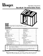
Horizontal Window Option With Offset Communication Conduit

The horizontal window wall panel is attached in three sections.
1.  Place the bottom panel section in position on the floor frame.
 

Attach it to the adjacent panel sections by turning the roto locks.

2.  Position the window panel section on top of the  

bottom panel section.


Attach the two sections together by turning  

the roto locks along the bottom edge of the  

window panel section.


Attach it to the adjacent panel sections by turning  

the roto locks.

3.  Position the top panel section on top of the  

window panel section.


Attach the two sections together by turning the roto locks  

along the top edge of the window panel section.


Attach it to the adjacent panel sections by turning the roto locks.

Horizontal Window Option With  

Straight-Through Communication Conduit

With this option, connections between the adjacent rooms must be made as the rooms  

are being assembled.

 The rooms must be positioned so the windows are directly opposite each other. 

1.  After one wall is erected in the first room, position the floor rail of the second room.
2.  Remove the conduit and fittings from the compartment inside the bottom panel section. 
3.  Place the bottom panel in the floor rail. 
4.  Assemble the three threaded  

conduit fittings as shown into the  

backs of both electrical boxes  

in both bottom panels. 

5.  Hold the second bottom panel  

vertical and measure the length  

of conduit required to connect  

the adjacent bottom panels. 

6.  Cut the conduit to the appropriate lengths  

and position them between the panels by  

rocking the second panel inward just  

far enough to position the conduit. 

7.  With all three conduit lengths positioned,  

re-plumb the panel, secure it by roto locking  

to the adjacent wall panel and continue  

assembling the next room.

Top Panel 

Section

Middle Window 

Panel Section

Bottom Panel 

Section

The window panel section is 

heavy. More than one person 

must lift it and set into place.

!

CAUTION

1-1/2” Conduit to  

Adjacent Room

Electrical 

Box

Male 

Adapter

Locknut

Cap

Attach 

Cover 

Plate

Bottom Panel 

Section

Electrical 

Box

Содержание SoundLok

Страница 1: ...Door 4 Fastener Parts List Ceiling 4 Fastener Parts List Closures 4 Electrical Connections 5 Installation 6 Floor Frame and Door Assembly 6 Floor Frame Leveling 10 Wall Panel Installation 11 Horizont...

Страница 2: ...ted States of America The information in this manual is subject to change without notice and does not represent a commitment on the part of Wenger Corporation Wenger Corporation does not assume any re...

Страница 3: ...oors requires four people working together CAUTION All electrical connections and electrical installation must be done by a licensed electrician WARNING The electrical source must be permanently wired...

Страница 4: ...ine Screw 20 x HOLE PLUG 3 Set Screw Allen 5 16 18 x Washer Neoprene x OD Washer 5 16 ID Capscrew 5 16 18 x Washer Flat Type A x 734 HOLE PLUG 3 4 PAI Capscrew 20 x Fastener Parts List Closures HOLE P...

Страница 5: ...ations of 120V 60 HZ 20 amp house service for a typical SoundLok layout The power panel includes a 20 6096 mm long cable that attaches to the distribution connector Requirements for electrical install...

Страница 6: ...the outline of the room leaving an opening for the door NOTE A corner section must be placed in each corner regardless of the door position and size If the optional Inset Floor is being installed foll...

Страница 7: ...utside edge on both sides of the door frame assembly using two 20 x machine screws in each bracket as shown Note Do not over tighten the machine screws as this could cause the door connect brackets to...

Страница 8: ...achine screws as shown The floor frame connect brackets may be aligned with the floor frame by inserting a screwdriver through the holes and prying into place 10 Apply a self adhesive gasket straddled...

Страница 9: ...y a minimum of 1 4 6 mm Positioning each leveling screw in the floor frame to be 3 16 5 mm or approximately 3 turns above the threaded insert heads is a good starting point The bottom of the floor rai...

Страница 10: ...st to adjust the outer leveling screws first then move in toward the middle Note Each leveling screw must contact the wall frame pad assembly c The rubber pad under the floor frame will compress sligh...

Страница 11: ...to locks located at the left hand inside edge of the wall panel section The roto locks are contained behind the inside skin panel Note The upper and lower roto locks turn in opposite directions This a...

Страница 12: ...rding to the layout plan drawing a Repeat Steps 3 and 4 locking the roto locks in the next wall panel section to the previously installed wall panel section b Continue to install the remaining wall pa...

Страница 13: ...d The rooms must be positioned so the windows are directly opposite each other 1 After one wall is erected in the first room position the floor rail of the second room 2 Remove the conduit and fitting...

Страница 14: ...open space above the door frame 2 Lightly engage the roto locks if present on each side of the header panel 3 Using a magnetic socket and the appropriate extensions install 5 16 18 x 3 4 capscrews fr...

Страница 15: ...ording to the layout plan drawing 2 Attach the beam to the top of the wall panels using a 3 8 neoprene washer a 5 16 flat washer and a 5 16 18 x 3 4 capscrew through each of the four pre drilled holes...

Страница 16: ...at the top of the wall panel 3 Working in a clockwise direction position the next ceiling frame rail with the end tab on top of the previously installed rail 4 Continue to install the remaining ceilin...

Страница 17: ...w through each of the pre drilled holes in the frame rail and into the cage nuts located underneath the skin of the ceiling panel Leave the ceiling panels loose to allow for adjustment while installin...

Страница 18: ...installed panel 5 Loosely attach the ceiling panel to the frame rail using a 1 4 flat washer and a 1 4 20 x 3 4 capscrew through both of the pre drilled holes in the frame rail and into the cage nut...

Страница 19: ...h the pre drilled holes using 8 15 x 5 8 pan head screws Note Connection to the building HVAC system must be made with an 8 203 mm diameter flexible duct NOT rigid duct Rigid duct will decrease the so...

Страница 20: ...rst followed by the corner sections 2 Tilt the inside ceiling trim down until the lower lip snaps over the bottom of the ceiling rail frame tab 3 Continue the process around the room until all of the...

Страница 21: ...instructions in 270A837 1 Inspect the dust box in the door frame to be sure that it is properly recessed behind the strike plate and will not interfere with the door latch bolt as it passes through th...

Страница 22: ...lide the vertical tab of the door assembly into the slot in the door frame Align the pre drilled holes in the door assembly with the corresponding pre drilled holes in the door frame Door Assembly The...

Страница 23: ...Installation continued Door Assembly continued 4 Loosely attach the door assembly to the door frame using a 3 8 16 x 1 socket screw in the five sets of aligned pre drilled holes 3 8 16 x 1 Socket Scr...

Страница 24: ...1 3 4 44 mm space between the inside face of the door frame and the inside of the door See Detail B Raise or lower the door assembly until the top of the inside door leaf is approximately 1 8 3 mm abo...

Страница 25: ...loosen the top and bottom mounting screws Adjust the hinge in the frame inward or outward at both the top and bottom to even the seal compression Re tighten the top and bottom mounting screws Repeat...

Страница 26: ...the screw in that area move the seal down and retighten the screw If there is too much resistance loosen the screw in that area raise the seal slightly and re tighten the screw 5 As a further check sh...

Страница 27: ...t seals Help the customer set appropriate expectations Check and correct the following until the door operates satisfactorily Dust box is sufficiently recessed Foam seals are in proper contact Magneti...

Страница 28: ...tion refer to the SoundLok Electrical Panel Interconnection Installation Manual Optional Communications Panel The communications panel has raceways from inside to outside that may be used for connecti...

Страница 29: ...h bracket 2 If the closure panel is being mounted flush to the ceiling attach a 2 x 4 metal stud to secure the top of the closure panel If there is no ceiling directly above the closure panel a 2 x 4...

Страница 30: ...of the pvc closure t extrusions b Remove and discard the adhesive backing from the pvc t extrusion and carefully apply it along the top edge of the wall panels 4 Cut the length of the pvc l closure ex...

Страница 31: ...t the front of the room a Apply two rows of self adhesive foam gasket to the metal stud surface making contact with the wall panel b Position the metal studs 1 1 8 29 mm back from the front surface of...

Страница 32: ...boards to fit the areas being covered b Secure the closure panels to the 2 x 4 metal studs using 12 x 1 self tapping screws leaving 3 mm space at the front to accomodate the thickness of the pvc closu...

Страница 33: ...ure panels c Cut the floor rail pvc extrusions to fit along the bottom edge of the closure panels d Remove and discard the adhesive backing from the pvc extrusions e Carefully apply the pcv extrusions...

Страница 34: ...s to distribute the lubricant Adjustments Magnetic door gasket to door stop Adjust only as necessary 1 Loosen the screws in the vertical and or horizontal door stops 2 If the gap is too tight tap stop...

Страница 35: ...he new pane of glass into the cavity be sure the surface to be placed between the panes is clean g Re seal the corners with soft sealant left over from disassembly h Replace the separators i Clean the...

Страница 36: ...door and then down will help avoid damage The gasket should be held up about 6 152 mm above the door so that it can be fed straight into the vertical retainers Sweep Seal Gasket Replacement 1 Remove t...

Отзывы: