


- 42 -
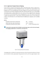
You can determine the center position and the width of the detection range for each position switch. The
position switches do not save their status but provide a momentary signal. To detect an end position reliably,
it must be ensured mechanically that the fingers block in the position that is to be detected, e.g. by a me-
chanical end stop or by the gripped part.
Merely traversing a position switch cannot be detected reliably due to the time-discrete sampling.
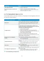
9.5
Gripping State
Besides detecting end positions via virtual position switches (cf. chapter 9.3), the gripping module also pro-
vides the “gripping state”. The gripping state is generated by the integrated gripped-part detection and is
transmitted to the cyclic process control via the cyclic process data. It can be used for the sequence control
of the handling process. Table 17 lists all possible gripping states. After startup, the module is in a special
“NOT INITIALIZED” state. The gripping module remains in this state until a reference run has been initiated.
State
State flag
Description
IDLE
IDLE = 1
Gripper Is Idle
The gripping module is inactive, and the fingers are force-free.
RELEASED
RELEASED = 1
Part Released
The part has been released, i.e. the parameterized RELEASE Limit has
been reached. The base jaws remain position-controlled in this posi-
tion with reduced force.
NO PART
NO PART = 1
No Part Gripped
No part has been detected while gripping, i.e. the parameterized
NO PART Limit has been reached. The base jaws remain position-con-
trolled in this position with reduced force.
HOLDING
HOLDING = 1
Part is being held.
The gripping module has been blocked between the parameterized
RELEASE Limit and NO PART Limit, and the base jaws do not move. The
part is held with the specified force; gripped-part monitoring is acti-
vated.
ERROR
FAULT = 1
An Error Has Occurred
An internal error that prevents the module from functioning correctly
has occurred. For information on error causes, see chapter 11.4. Addi-
tionally, a system event has been triggered, see Table16.
Table 17: Gripping states
In regular operation, depending on the command executed last and the current position of the base jaws,
one of four gripping states can be reached: IDLE, RELEASED, NO PART, or HOLDING. The FAULT state indicates
a device error. The possible transitions between the states are depicted in Figure 13.
A change of state is initiated by the gripping commands GRIP/RELEASE and ENABLE/DISABLE, which are set
by the master via the cyclic process data. When the gripping module receives a new command, the command
Содержание 5120012
Страница 1: ...Mounting and Operating Manual CRG Series Electrical Gripping Modules with IO Link October 2020...
Страница 63: ...62 Figure 22 Configuration of the IO Link master Figure 23 Starting the S7 PCT port configurator device tool...
Страница 64: ...63 Figure 24 Configuration of the IO Link port...