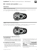
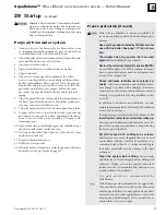

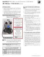
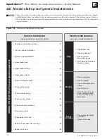

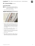

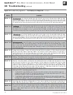
Figure 101
Throttle adjustment screw
––
(ONLY for use by a qualified technician, using
calibrated combustion test instruments).
Part number 550-100-305/0118
77
AquaBalance
TM
W
ALL
M
OUNT
GAS
-
FIRED
WATER
BOILER
—
Boiler Manual
30
(continued)
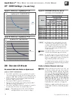
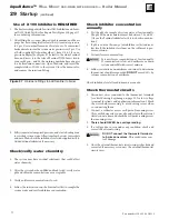
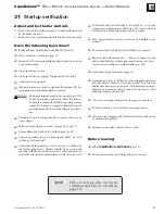
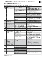
Figure 102
Maximum rate
combustion values –
measured values must be within the ranges
given below
Using a
combustion analyzer check the CO
2
values at low and high fire. It should be within
values from the table in Figure 102. The differ-
ence of CO
2
from high fire to low fire should
NEVER
be below 0.2% or above 1%.
DO NOT
attempt to adjust the throttle screw
unless by a qualified technician, and with the
use of calibrated combustion test instruments.
Adjust the throttle screw only as needed to meet
the combustion values given in Figures 102 and
105, page 78.
Adjust in steps of no more than 1/8 of a turn and
wait 1 minute after each adjustment to allow the
setting to stabilize. Turning the screw too far will
cause the adjustment to reverse behavior.
4. In the event that the CO
2
setting level with an acceptable
CO/CO
2
ratio cannot be obtained please contact your
Weil-McLain Technical Support for details.
5. Should you require any assistance during the set up pro-
cedure contact your Weil-McLain Technical Support if
the problem cannot be addressed with the information
provided in this manual.
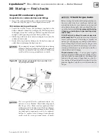
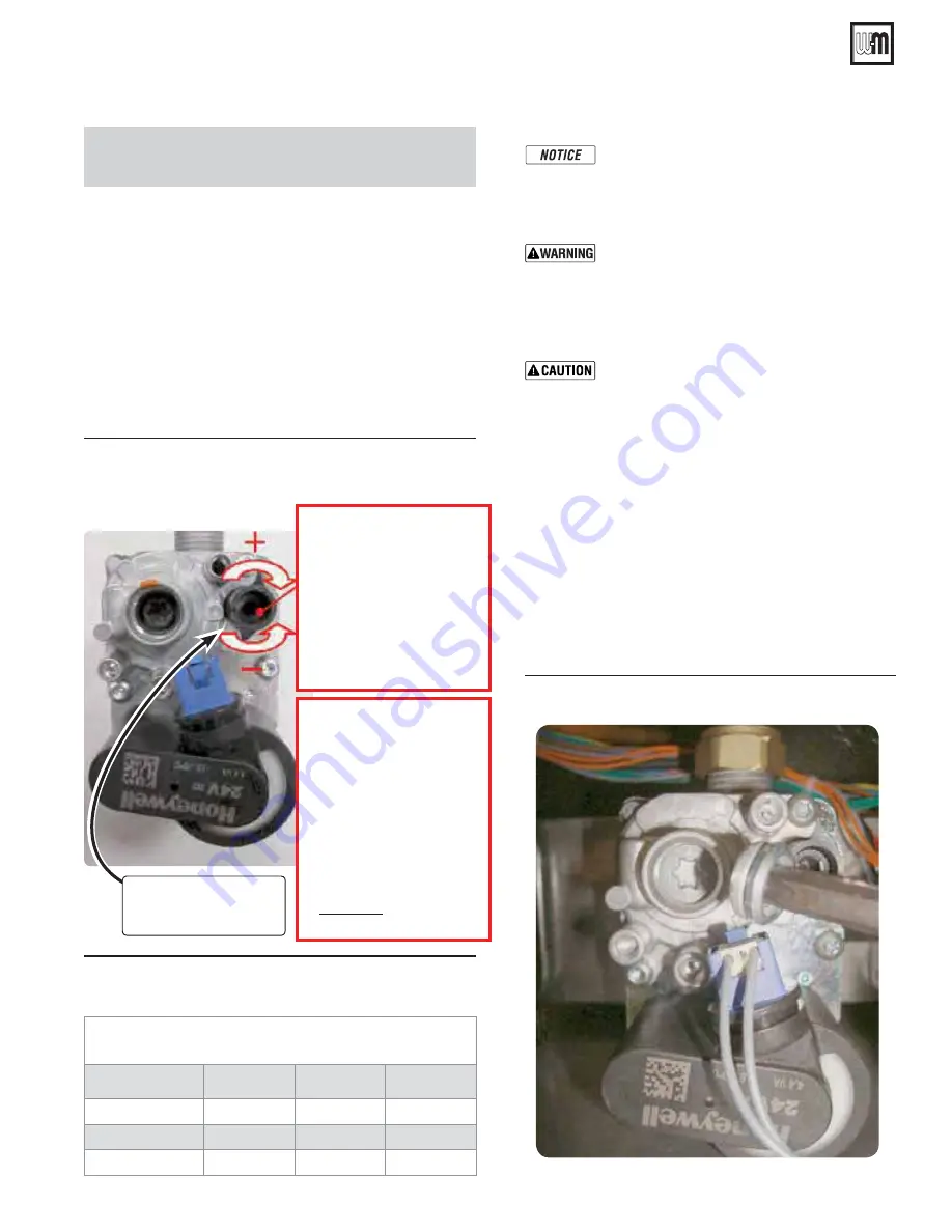
6. Remove T-40 cap, see Figure 103, below, for Offset screw
adjustment.
Natural Gas/LP Acceptable
Combustion Range
Maximum Rate after 10 minutes from cold
Boiler Model
CO/(PPM)
CO
2
NG %
CO
2
LP %
WMB-80
110
9.0 – 9.5
10.2 – 10.7
WMB-120
110
9.0 – 9.5
10.2 – 10.7
WMB-155
120
9.0 – 9.5
10.2 – 10.7
Setting the Air/Gas Ratio valve
There are two adjustments possible on the air/gas ratio valve,
the throttle setting at Maximum rate and the offset setting at
Minimum rate. If either setting is adjusted the combustion values
must be rechecked at both rates.
At Maximum Rate:
1. Adjust the boiler to Maximum rate in Figure 99, page 74,
Test Mode.
2. Wait 10 minutes to allow the boiler to stabilize.
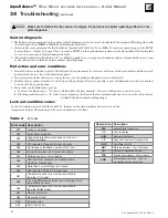
3. Now adjust the Throttle setting (Figure 101 - screw A) until
the CO
2
is at the correct SETTING LEVEL (see Figure 102),
below confirm that the CO/CO
2
ratio is within limits (clock-
wise to increase gas).
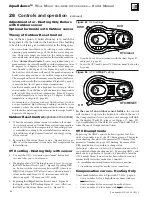
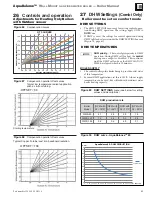
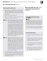
Figure 103
Remove
T-40 cover cap with supplied Torx
wrench for adjustment
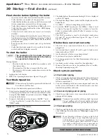
Throttle adjustment
screw
A
CO
2
Max. Regulating screw
Test at Max Power 100%
Turn clockwise (open gas)
!"#$;=
Turn counter-clockwise
(close gas)
>?!"#$;=
Rough start point
For LP Start up ONLY
Adjust gas valve
HIGH FIRE
screw on right with
Allen wrench turn
Counter-Clock wise
1-1/8 turns.
Final Combustion values
MUST BE
checked with
Combustion Analyzer.