


Part number 550-100-305/0118
54
AquaBalance
TM
W
ALL
M
OUNT
GAS
-
FIRED
WATER
BOILER
—
Boiler Manual
23
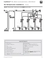
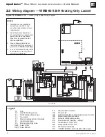
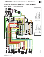
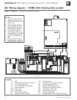
Wiring diagram — WMB-80/120H Heating Only Ladder
Figure 70
WMB-
80/120H –– Heating Only Ladder Wiring Diagram
Legend
16 Fan
32
Central heating pump
42
DHW temperature sensor
44
Gas valve
72
Room thermostat (not included)
81
Ignition electrode
95
Mixing (diverting) valve
104(1)
Fuse
3.15A
104 (1) Fuse 630mA
114
Water pressure switch
136 Flow
meter
138
Outside temperature sensor (optional on Combi)
186
Return temperature sensor
191
Exhaust temperature sensor
278
Double sensor (h safety)
279
Transformer 115-24 VAC
284
Relay SPST-Coil 24 VAC
370
LWCO (not included)
373
“OPENTHERM” communication (Not used)
cod. 3541M870
NOTES:
1. All wiring must be installed in
accordance with N.E.C. and
any other national state or local
requirements.
2. Room thermostat should be a
dry contact type and should draw
power from the control board:
should not be greater than
24
VAC and 500 mA
.
3. Max. voltage and electric cur-
rent for the LWCO should not be
greater than
120VAC and 3 Amp.
4. In case of questions during instal-
lation please contact your local
Weil-McLain distributor.