Weil-McLain Aqua Balance WMB-120 Скачать руководство пользователя страница 53

Part number 550-100-305/0118

 53 

AquaBalance

TM


W

ALL

 M

OUNT


GAS

-

FIRED


WATER


BOILER

 — 

Boiler Manual

22  

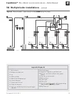
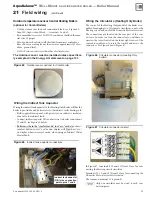
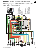
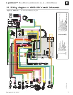
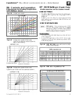
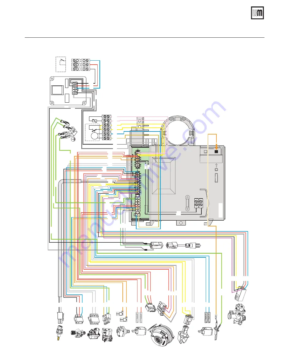
Wiring diagram — WMB-80/120C Combi Schematic

Figure 69


WMB-

80/120C –– Combi Schematic Wiring Diagram


ABM08

X3 - 12 X3 - 10 X3 - 1

1

X3 - 24 X3 - 22 X3 - 23

X3 - 6

X3 - 2

X3 - 13

X3 - 1

X2 - 5

X2 - 11

X4 - 8

X4 - 17

X4 - 5

X4 - 13

X4 - 12

X4 - 4

X2 - 7

X3 - 12

X3 - 24

X3 - 11

X3 - 23

X3 - 10

X3 - 6

X3 - 13

X3 - 2

X3 - 1

X4 - 8

X4 - 17

X2 - 1

1

X2 - 5

X4 - 13

X4 - 5

X4 - 4

X4 - 12

X2

1

12

13

24

X3

1

9

10

18

X4

61

12

7

191

136

44

32

11

4

X3 - 18

X3 - 18

95

X3 - 5

X3 - 17

X3 - 4

X3 - 16 X3 - 4

X3 - 17

X3 - 5

X3 - 22

X3 - 8

X3 - 20

X3 - 7

X3 - 19

X3 - 8

X3 - 20

X3 - 7

X3 - 19

X2 - 4

X2 - 10

X2 - 10

X2 - 4

GROUND

X3 - 9

X3 - 21

186

X3 - 9

X3 - 21

42

278

16

GROUND

X4 - 6

X4 - 15

X4 - 6

X4 - 15

GROUND

X2 - 12

X2 - 6

X1 - 1

X1 - 2

X4 - 3

X4 - 11

X4 - 2

X4 - 10

X1

81

373

1

2

GROUND

GROUND

GROUND

X2 - 1

GROUND

120Vac

60Hz

GROUND

370

138

(see note 3)

M

1

61

0

5

279

284

104 (2)

X4 - 7

X4 - 1

72

(see note 2)

X0

R

W
C

TT

X0 - 10

X0 - 9

X0 - 8

X0 - 1

X0 - 6

X0 - 5

X0 - 4

104 (1)

12

3

4

5

6

.(<

$

%##

&'*

#

%

+

;#<=

&

$>?@

$D>E@

*

#!

$!

H

+#

=J#

&O

Q

?Y[


+;\;Q

Y%[


]!*

%


^H\=_Q'=+`  

Содержание Aqua Balance WMB-120

Страница 1: ...chnician Failure to comply could result in severe personal injury death or substantial property damage When calling or writing about the boiler Please have boiler model number from the boiler rating l...

Страница 2: ...etts installations 20 8 Vent termination requirements 21 9 Boiler room air openings 22 10 DIRECT VENT Sidewall with separate pipes 23 11 DIRECT VENT Sidewall concentric 25 12 DIRECT VENT Vertical with...

Страница 3: ...ll secure sealed and installed as instructed in this boiler manual Central Heating only boilers Outdoor sensor MUST be installed and connected to the boiler control See page 51 System start 1 Push eco...

Страница 4: ...sold separately see Figure 158 page 116 High altitude High altitude over 4 500 feet requires only changing the altitude setting on the control See page 67 Equipment that maybe required for installatio...

Страница 5: ...ld weather boiler system components failures power out ages or other electrical system failures could result in frozen plumbing and water damage in a matter of hours For your protection take preventat...

Страница 6: ...If the boiler is located in a residential garage Mount the boiler with its burner and igniter are at least 18 inches above the oor Follow the National Fuel Gas Code ANSI Z223 1 for U S installations o...

Страница 7: ...se air openings must have free area of at least 1 square inch per 1 000 MBH of boiler input B Left side clearance to combustibles 1 0 inches minimum C Top of boiler clearance to combustibles 12 0 inch...

Страница 8: ...ble 1 Corrosive contaminants and likely locations You must pipe combustion air to the boiler air intake Install air inlet piping for the boiler as described in this manual The air termination tting mu...

Страница 9: ...s on 16 inch centers Forotherstudspacing providesecure solidmounting surface on which to attach the boiler wall mounting bracket 2 Wood stud wall Install bracket with lag screws 3 8 x 3 included in ki...

Страница 10: ...ug in the relief valve tapping After the hydrostatic test this plug must be removed and the relief valve must be installed Fill and pressure test 1 See Figure 6 page 11 for use with the following inst...

Страница 11: ...ller Optional can use boiler gauge 5a Reducing tee 1 x 1 x on WMB 80 120 NPT 1 1 4 x 1 1 4 x on WMB 155 eld supplied by installer 5b Tee NPT 1 x 1 x on WMB 80 120 NPT 1 1 4 x 1 1 4 x on WMB 155 eld su...

Страница 12: ...ekit Follow all instructions in proper order Do not tamper with venturi DO NOT change or modify venturi in any way Do not leave an uninstalled venturi in the building Caution the gas supply shall be s...

Страница 13: ...contact gas supplier to correct the problem before attempting to start or operate the boiler Installing venturi If boiler is already installed You must turn off electrical supply to the boiler and cl...

Страница 14: ...e venturi Item 5 in place remove venturi replace with new propane venturi from kit Verify the venturi label information matches the boiler size WMB 80 120 155 Propane ven turi has black label ensure I...

Страница 15: ...23 1 NFPA 54 latest edition and or the Natural Gas and Propane Installation Code CAN CSA B149 1 12 Using a combustion analyzer insert probe into the flue test point check that the CO2 content in the e...

Страница 16: ...ust lockup regulator for 13 w c maximum Propane Gas You must follow the instructions beginning on page 12 to operate the boiler on propane Failure to comply could result in severe personal injury deat...

Страница 17: ...ppliances remaining on the old common vent system Vent system veri cation Perform the test sequence below for each appliance remaining on the original common vent system Operate each appliance indi vi...

Страница 18: ...e inches Materials Fig 21 page 19 Size inches Materials Fig 21 page 19 Size inches Materials Fig 21 page 19 Size inches Materials Fig 21 page 19 WMB 80 2 PVC PVC DWV CPVC PP SS 2 PVC PVC DWV CPVC PP S...

Страница 19: ...tailed information MUST USE LOCKING COLLAR ON EVERY JOINT ULC S636 PVC PVC DWV CPVC or polypropylene AL29 4C stainless steel piping materials Vent pipe AL29 4C stainless steel Heat Fab Inc Saf T Vent...

Страница 20: ...ing appliance or equipment The sign shall read in print size no less than one half 1 2 inch in size GAS VENT DIRECTLY BE LOW KEEP CLEAR OF ALL OBSTRUCTIONS 4 INSPECTION The state or local gas inspecto...

Страница 21: ...d or the Natural Gas and Propane Installation Code CAN CSA B149 1 The vent termination clearances below are for U S A for Canadian vent termination clearances please refer to the requirements of CAN C...

Страница 22: ...e room Unless speci ed otherwise by appliance manufacturer TWO openings each at least 1 square inch per 4 000 Btuh of all other appliances in the room OR ONE opening each at least 1 square inch per 3...

Страница 23: ...l lation Code and a ULC S636 compliant vent kit 3 The air inlet of a boiler is part of a direct vent connection It is not classi ed as a forced air intake with regard to spacing from adjacent boiler v...

Страница 24: ...ir ter mination elbow by inser ting bird screens See Figure 25 page 23 Bird screens must be purchased separately See the parts list at the end of this manual for part numbers 2 Secure the elbows so th...

Страница 25: ...he same height to avoid possibility of severe personal injury death or substantial property damage 2 Place wall penetrations to obtain minimum clear ance as shown in Figure 29 page 26 for U S installa...

Страница 26: ...n Figure 30 4 Before beginning vent and air piping from the boiler to the con centric termination mount and secure the concentric termination as shown in Figure 30 The vent and air piping must be secu...

Страница 27: ...e short radius elbows for vent or air piping Boiler performance could be affected Part number 550 100 305 0118 27 AquaBalanceTM WALL MOUNT GAS FIRED WATER BOILER Boiler Manual Allowable vent air pipe...

Страница 28: ...ots sized for the vent pipe and air pipe Follow all vent pipe manufacturer s instructions Termination and ttings 1 Prepare the vent termination elbow and the air termina tion elbow Figure 31 page 27 b...

Страница 29: ...in this manual All vent outlets must terminate at the same height to avoid possibility of severe personal injury death or substantial property damage 2 Place roof penetrations to obtain minimum cleara...

Страница 30: ...k to form The vent and air piping must be securely supported and must not rest its weight on the boiler ttings DO NOT drill or screw into either the vent pipe or air pipe Failure to properly support t...

Страница 31: ...and all supports have been installed Follow instructions to cover the end of the assembly with plastic before inserting through the roof penetration to prevent debris from blocking the air passages I...

Страница 32: ...he lengths given in the previous pages for either the air or vent piping 2 See Figure 37 for locations for attaching vent and air inlet adapters on to the boiler Air inlet adapter connection is made o...

Страница 33: ...ch cement on sockets to prevent cement buildup inside With cement still wet insert pipe into tting twist ing turn Make sure pipe is fully inserted Wipe excess cement from joint Check joint to be sure...

Страница 34: ...ther for 10 seconds 2 At the end of the 10 seconds the display will show the mes sage b01 15 Vent and air piping and boiler connections continued Push DHW buttons together for 10 seconds DHW Press Hea...

Страница 35: ...re relief valve that complies with the standard for relief valves and automatic gas shut off devices for Hot Water Supply Systems ANSI Z21 221 CSA4 4 is required to be installed at the supply DHW conn...

Страница 36: ...al reset limit i e set control no higher than 180 F for a 200 F external limit for example Back ow preventer Use back ow preventer in the cold water supply piping if required by local codes System zon...

Страница 37: ...oiler and system water volume and temperature See tank manufacturer s instructions and ratings for details Additional tanks may be added to the system if needed to handle the expansion These tanks may...

Страница 38: ...4 Pipe 1 Pipe 3 4 Pipe 1 Pipe 1 1 4 Pipe WMB 80 HEAT ONLY 20 7 4 7 8 12 5 3 0 20 3 10 8 A B C D ___ 30 4 9 4 0 6 0 1 5 10 0 5 5 B C D E B C D E 40 3 7 2 7 3 5 0 8 6 2 3 5 B C D E B C D E WMB 120 HEAT...

Страница 39: ...due to over pressurization NEVER use an automatic air vent in a system equipped with a closed type expansion tank The air removed from the system will cause water logging of the expansion tank Closed...

Страница 40: ...charge Locate away from the top of the boiler Discharge line must be as short as possible and be the same size as the valve discharge connection throughout its entire length Discharge line must pitch...

Страница 41: ...y installer capable of delivering the proper ow and head as shown Expansion Tank required 1 Provide a system expansion tank following the guidelines on pages 37 or 39 2 DO NOT use a closed type tank i...

Страница 42: ...nputs and outputs intended for DHW applications may violate Section 303 of the 2007 Energy Act See page 131 for compliance information and exemptions Wiring the Indirect tank aquastat to the Heating O...

Страница 43: ...regulates supply temperature to the lower temp zones Boiler operation for fan coil only applica tions parameter P02 page 95 may be set to 20 for faster ramp up to boiler set point temperature Domesti...

Страница 44: ...ns are not possible provide at least the minimum clearances given on page 5 Also follow local codes 3 Provide a minimum 36 inch walkway in front of the boilers to ensure accessibility 4 Unpack assembl...

Страница 45: ...or 5 Expansion tank diaphragm type 6 System air eliminator 7 System automatic air vent 8 Pressure reducing valve 9 Check valve or back ow preventer as required by appli cable codes 10 Cold water suppl...

Страница 46: ...ile the last boiler delivers DHW priority 2 Pipe from the near boiler piping to the DHW tank s boiler connections as shown in Figure 50 page 41 3 Connect the DHW tank aquastat directly to the DHW inpu...

Страница 47: ...omply with ASTM D2564 or F493 For Canada use CSA or ULC certi ed PVC or CPVC pipe ttings and cement 2 Select a condensate pump if used that is approved for use with condensing boilers and furnaces The...

Страница 48: ...oiler or its ac cessories 5 Purge all air from gas supply piping 6 Before placing boiler in operation check boiler and its gas connection for leaks a During any pressure testing at less than 13 w c cl...

Страница 49: ...ances in the property working Measure the gas rate Measure the gas rate and check against following Table 2 For natural gas or lique ed petroleum propane gas the pres sure required at gas valve inlet...

Страница 50: ...ust be electri cally bonded to ground in accordance with the requirements of the authority having jurisdiction or in the absence of such requirements with the National Electrical Code ANSI NFPA 70 lat...

Страница 51: ...lve for indirect tank Connect indirect aquastat N O contact wires to boiler connections 7 and 8 see Figure 65 below Boiler must be in the comfort mode not eco mode push eco comfort button to exit eco...

Страница 52: ...Combi 186 Return temperature sensor 191 Exhaust temperature sensor 278 Double sensor heating safety 279 Transformer 115 24 VAC 284 Relay SPST Coil 24 VAC 370 LWCO not included 373 OPENTHERM communicat...

Страница 53: ...17 X2 11 X2 5 X4 13 X4 5 X4 4 X4 12 X2 1 12 13 24 X3 1 9 10 18 X4 6 1 12 7 191 136 44 32 114 X3 18 X3 18 95 X3 5 X3 17 X3 4 X3 16 X3 4 X3 17 X3 5 X3 22 X3 8 X3 20 X3 7 X3 19 X3 8 X3 20 X3 7 X3 19 X2...

Страница 54: ...nal on Combi 186 Return temperature sensor 191 Exhaust temperature sensor 278 Double sensor heating safety 279 Transformer 115 24 VAC 284 Relay SPST Coil 24 VAC 370 LWCO not included 373 OPENTHERM com...

Страница 55: ...ND X3 6 X4 8 X4 17 X4 5 X4 13 X4 12 X2 7 X3 18 X3 5 X3 17 X3 4 X3 16 X3 8 X3 20 X3 7 X3 19 X2 4 X2 10 X2 12 X2 6 X2 1 X4 4 X4 7 X4 1 X1 1 X1 2 X4 3 X4 11 X4 2 X4 10 X3 9 X3 21 X2 5 X2 11 GROUND X2 3 X...

Страница 56: ...l on Combi 186 Return temperature sensor 191 Exhaust temperature sensor 278 Double sensor heating safety 279 Transformer 115 24 VAC 284 Relay SPST Coil 24 VAC 370 LWCO not included 373 OPENTHERM commu...

Страница 57: ...ure sensor 44 Gas valve 72 Room thermostat optional 81 Ignition electrode 95 Mixing diverting valve 104 1 Fuse 3 15A 104 2 Fuse 630mA 114 Water pressure switch 136 Flow meter 138 Outside temperature s...

Страница 58: ...Return temperature sensor 191 Exhaust temperature sensor 278 Double sensor heating safety 279 Transformer 115 24 VAC 284 Relay SPST Coil 24 VAC 370 LWCO not included 373 OPENTHERM communication Not u...

Страница 59: ...NT GAS FIRED WATER BOILER Boiler Manual Figure 75 WMB 155H Heating Only Schematic Wiring Diagram 25 Wiring diagram WMB 155H Heating Only Schematic cod 3541M930 Only one circula tor may be wired to eac...

Страница 60: ...ystem with advanced self diagnosis unit operation is for the most part automatic The system heating temperature is automatically governed by the control system The display continuously provides inform...

Страница 61: ...The display indicates the actual Central Heating water temperature Item 10 Figure 76 page 60 and when the required set point temperature is reached d2 will be displayed NOTE Heating Only boilers must...

Страница 62: ...ver the external controls are calling for heat Figure 81 Power down mode Power down mode Press the on off button Item 7 Figure 76 page 60 for 5 seconds To totally isolate close the gas cock before the...

Страница 63: ...high hot water delivery speed and excellent user comfort When comfort mode is active the water in the boiler is maintained at a pre determined temperature which means that hot water is available at t...

Страница 64: ...and energy saving all year round 2 By using the CH buttons Items 3 and 4 Figure 84 it is pos sible to set the maximum system water ow temperature for the installation OTC setting Heating Only with sen...

Страница 65: ...is used the settings for control operation during DHWcallsforheataresetundertheDHWSETTINGSmenus Figure 78 page 61 DHW TEMPERATURES DHW priority ThecontrolgivesprioritytoDHW operation During DHW call f...

Страница 66: ...til the parameter b04 is on the screen 3 Set parameter b04 to parameter in Table above 4 Repeat steps 2 and 3 above to also adjust parameter b05 and b06 according to Table above 5 Press DHW and DHW bu...

Страница 67: ...6 000 44 8 0 9 0 20 155 9 0 9 5 110 6 000 7 000 45 8 0 9 0 20 155 9 0 9 5 110 7 000 8 000 46 8 0 9 0 20 155 9 0 9 5 110 8 000 9 000 47 8 0 9 0 20 155 9 0 9 5 110 9 000 10 000 48 8 0 9 0 20 155 9 0 9...

Страница 68: ...8 0 8 5 20 200 8 7 9 0 150 7 000 8 000 52 8 0 8 5 20 200 8 7 9 0 180 8 000 9 000 53 8 0 8 5 20 200 8 7 9 0 180 9 000 10 000 54 8 0 8 5 20 200 8 7 9 0 180 120KBTU LP Gas ALTITUDE LOW FIRE HIGH FIRE CH...

Страница 69: ...4 000 42 9 0 9 8 7 210 10 2 10 7 120 4 000 5 000 43 9 3 9 5 10 210 9 7 9 9 150 5 000 6 000 44 9 3 9 5 10 210 9 7 9 9 150 6 000 7 000 45 9 3 9 5 10 210 9 7 9 9 150 7 000 8 000 47 9 3 9 5 10 210 9 7 9...

Страница 70: ...zoned systems ush each zone separately through a purge valve If purge valves and isolation valves are not already installed install them to properly clean the system 2 Flush system until water runs cl...

Страница 71: ...y these products or instructions for other applications Local codes may require a back ow preventer or actual discon nection from city water supply Part number 550 100 305 0118 71 AquaBalanceTM WALL M...

Страница 72: ...d and corrected if necessary reconnect the external thermostat circuit wires Part number 550 100 305 0118 72 AquaBalanceTM WALL MOUNT GAS FIRED WATER BOILER Boiler Manual 29 Startup continued Figure 9...

Страница 73: ...ck for damages occurring from water accumulation in this cabinet Any damaged components need to be replaced Failure to replace water damaged components could result in severe personal injury or death...

Страница 74: ...vate the TEST mode 3 The boiler lights at the maximum heating 100 rate displayed on the LCD display 4 The high re large ame symbol will be displayed once the boiler has lit 5 Use DHW button to drop ri...

Страница 75: ...erating instructions WARNING Verify that the control is set for the correct boiler model before proceeding Part number 550 100 305 0118 75 AquaBalanceTM WALL MOUNT GAS FIRED WATER BOILER Boiler Manual...

Страница 76: ...values must comply with or Figure 105 page 78 If results are acceptable proceed to step 7 IF NOT follow the instructions under Throttle Screw Adjustment on page 77 to set the throttle screw posi tion...

Страница 77: ...contact your Weil McLain Technical Support if the problem cannot be addressed with the information provided in this manual 6 Remove T 40 cap see Figure 103 below for Offset screw adjustment Natural G...

Страница 78: ...provided in this manual Check ignition system safety shutoff device 1 After the boiler has been installed turn off the boiler 2 Shut off the manual gas valve located on the gas line to cut ow of fuel...

Страница 79: ...tional eld installed controls tested as outlined by control manufacturers Boiler should be operating and should go off when controls are tested Verify controls cause automatic reset lockout or manual...

Страница 80: ...throughout this manual and in component literature shipped with the boiler Failure to perform the service and maintenance could result in damage to the boiler or system Failure to follow the directio...

Страница 81: ...pages 49 and 77 d The gas rate as described on page 49 e The combustion performance as described on pages 76 77 and 78 for combustion check f Competence to carry out the check of combustion per forman...

Страница 82: ...ove any obstructions Do not use solvents to clean any of the boiler components The components could be damaged resulting in unreliable or unsafe operation Check all piping for leaks Eliminate all syst...

Страница 83: ...ion is properly adjusted turn off boiler and allow boiler to cool down Then remove burner andcleanitthoroughlyusingavacuumcleanerorcompressed air Do not use compressed air to clean burner if performed...

Страница 84: ...to the valve rendering it inoperative When manually operating the lever water will discharge and precautions must be taken to avoid contact with hot water and to avoid water damage Before operating le...

Страница 85: ...0mm wrench Remove heat exchanger cover plate 20 long handled Torx driver Remove burner screws T 40 Torx driver For gas valve Offset Low re adjustment 4mm Allen wrench For gas valve High re adjustment...

Страница 86: ...e time It is the time that the fan takes to reach the ignition level to effectively purge boiler venting 4 Ignition There are 0 2 seconds of preignition where the control checks the status of the gas...

Страница 87: ...ajor components blower etc If a fuse is blown it can prevent the con trol or other components from operating 1 Turn OFF power to boiler at external line switch Then remove the jacket door 2 Locate fus...

Страница 88: ...ut condition codes A codes which blocks the heat demand Press reset button for 1 second to reset b Blocking condition codes F codes cause temporary shutdowns that are automatically reset as soon as th...

Страница 89: ...he heating sensor No water circulation in the system Check the circulating pump Air in the system heat exchanger Vent the system purge heat exchanger A04 Exhaust duct safety device activation Fault F0...

Страница 90: ...wards return side of boiler Check pump location and pump water direc tion F39 Outdoor sensor fault Sensor damaged or wiring shorted Check the wiring or replace the sensor Sensordisconnectedafteractiva...

Страница 91: ...F35 Frequency error F37 The water pressure in the CH installation is too low F39 Outside sensor error F40 The water pressure in the CH installation is too high or there s a Control fault F43 Heat exc...

Страница 92: ...X X case speed is back to the normal operating range error is gone In error mode heat demands will be disabled Resolving situation can be achieved only if the speed is within operating range again FAU...

Страница 93: ...s back into the normal operation Each CH or Installer Test mode demand jX QX jX X Z Q X X Z ZX j XZ jX QX jX X Z Q X X Z ZX X Z X ZX X X j X jX X jX Q X X Z ZX X ZX X X X Z X QQX X Z X XZ X X jX QX jX...

Страница 94: ...18 Z ZX X J Z QXZX X J Z QXZX X J Z QXZX X J 15 DHW conf dependent b19 X Q X X J X X Z X Z J X Q X X J X X Z X Z J 0 0 0 0 DHW conf dependent b20 Q X X XQX Z 1 b21 Pump protection time Sec 5 b22 PVC C...

Страница 95: ...rent parameter mode Do NOT change settings In blinking Inquiry mode Hi blinking History mode rE blinking Reset all the History information Parameter Description Default Note P01 Ignition level 60 60 W...

Страница 96: ...maximum output 100 P21 Z ZX J Z QXZX X J Z QXZX X J Z QXZX X J 20 DHW conf dependent P22 Z ZX J Z QXZX X J Z QXZX X J Z QXZX X J 42 DHW conf dependent P23 Blower speed in Stand by mode Hz 0 P24 Post V...

Страница 97: ...b05 b06 b10 b12 P01 P02 P04 Gas type Boiler type Fan Max Freq in DHW Fan Max Freq in CH Fan Min Freq in CH S W mode selection button Var Out Relay Ignition level CH Slope F min CH Off Time WMB 80 N C...

Страница 98: ...ion has been taken the MMI automatically leaves this mode after 15 minutes P10 blinking Actual water pressure psi P11 blinking Actual PWM modulating Pump P12 blinking Actual Step of Triac mod mode Num...

Страница 99: ...irmware version Num 0 99 03 9 1 CL5 066E DHW P factor Num 0 255 15 10 1 CL5 0691 DHW I factor Num 0 255 240 11 1 ML 80EB DHW FF factor Num 0 255 0 12 1 ML 80EC Fan absolute DHW maximum speed Hz 0 220...

Страница 100: ...eed Hz 0 220 200 14 2 ML 80EE Fan absolute minimum speed Hz 0 165 40 15 2 CL5 2D89 Fan offset low level Hz 0 220 10 16 2 ML 80F0 Ignition level 0 100 60 17 2 Free TBD 18 2 Free TBD 19 2 Free TBD 20 2...

Страница 101: ...p_burnerOFF solar F 0 200 18 24 3 ML 80F8 DHW over temp_burnerON solar F 0 200 18 25 3 ML 80F9 DHW start waiting time solar1 Sec 0 255 5 26 3 ML 80FA DHW start waiting time solar2 Sec 0 255 10 27 3 ML...

Страница 102: ...time Sec 30 255 120 33 4 CL5 0A04 DHW pump over run time Sec 0 255 30 34 4 CL5 0A6D Delta T1 F 0 108 32 35 4 CL5 0A92 Delta T2 F 0 255 63 36 4 ML 8104 CH supply for CH pump over run OFF F 32 212 68 3...

Страница 103: ...tem 75 ML 8128 X QQ Z X Num 0 1 0 System 76 ML 811B Main supply frequency Num 0 1 1 System 77 ML 80DC Variable output relay functionality Num 0 8 0 System 78 ML 812A External pcb variable output relay...

Страница 104: ...ML 8031 Hour when History error 5 is happened MSB Num History 119 ML 8036 Hour when History error 6 is happened LSB Num History 120 ML 8035 Hour when History error 6 is happened MSB Num History 121 M...

Страница 105: ...157 1 ML 80D8 Peak pump switch on time Sec 0 255 20 158 1 ML 80CD Peak remove time Sec 0 20 0 159 1 ML 80CE Peak remove switch off temperature F 32 212 194 160 1 ML 80CF Peak pump speed 0 100 100 Syst...

Страница 106: ...t OpenTherm 19 CL4 FAF4 LSB OT room setpoint F Dec OpenTherm 20 CL4 FAC8 MSB OT room temp F Int Figure 134 Troubleshooting suggestions for AquaBalance boilers Fault displays and diagnostics continued...

Страница 107: ...Discon nect all electrical power to the boiler before attempting maintenance pro cedures Failure to complete could result in severe personal injury death or substantial property damage Jacket side pa...

Страница 108: ...nnot be cleaned satisfactorily replace ignitor If the igniter ceramic is cracked or damaged replace 7 Reinstall ignition electrode making sure gasket is in good condition and correctly positioned TORQ...

Страница 109: ...rogen from the inside out clean with a water spray from inside the burner swirl the burner thoroughly in a bucket of mild liquid laundry detergent water then rinse thoroughly Use ONLY a non metallic b...

Страница 110: ...to remove any accumulation on the heating surfaces This includes removing any pieces of refrac tory that may have dropped into the heat exchanger Figure 145 Cleaning the heat exchanger Figure 146 Cle...

Страница 111: ...in an appropriate manner in accordance with current standards Before installation of the boiler carefully ush all the pipes of the system to remove residues or impurities that could affect the proper...

Страница 112: ...es of the pump from the 3 4 NPT Heat exchanger system delivery 1 and Heat exchanger system return 5 connections Reconnect the system piping to 3 4 NPT Heat exchanger system delivery 1 and Heat exchang...

Страница 113: ...c hot water circuit in the boiler by opening a hot water tap downstream of the boiler Wait until heat exchanger boiler is cooled down before proceeding Water in brazed plate heat exchanger may still b...

Страница 114: ...ate removal The gas valve does NOT need to be removed to replace brazed plate heat exchanger 4 Flat plate heat exchanger can be immersed in a chemical clean ing bath Combi 80 120 at plate heat exchang...

Страница 115: ...to seal brazed plate heat exchanger 1 Slide the brazed plate heat exchanger into rear of enclosure orientation arrows pointing down 2 Lift brazed plate heat exchanger slightly up and align with DHW c...

Страница 116: ...eplacement part Results from us ing modi ed or other manufactured parts will not be covered by warranty and may damage boiler or impair operation The boiler contains ceramic ber materials The boiler c...

Страница 117: ...concentric vent kit horizontal or vertical includes components for concentric assembly Kit for 2 PVC vent and air pipes Kit for 3 PVC vent and air pipes 383 700 167 383 500 350 Bird screens 1 screen e...

Страница 118: ...AquaBalanceTM WALL MOUNT GAS FIRED WATER BOILER Boiler Manual 36 Replacement parts continued Item Name Part Number 100 Jacket door 640 000 067 110 Jacket left side 640 000 065 120 Jacket right side 64...

Страница 119: ...odule assembly 640 000 003 110 Control module display cover 640 000 004 120 Pressure Temperature assembly 640 000 006 130 Wire harness assembly Combi 80 120 640 000 005 Wire harness assembly Combi 155...

Страница 120: ...18 250 Water Pressure Switch 640 000 019 260 Flow Meter 640 000 026 270 Water Filter 640 000 027 280 Valve 3 Way 640 000 028 290 Motor 3 Way Valve 640 000 029 300 N R Valve Fitting 640 000 030 310 DHW...

Страница 121: ...Part number 550 100 305 0118 121 AquaBalanceTM WALL MOUNT GAS FIRED WATER BOILER Boiler Manual 36 Replacement parts continued Figure 163 Boiler replacement kits and parts WMB 80 120C Combi continued...

Страница 122: ...80 Burner Cover 640 000 016 190 Inspection Glass 640 000 015 200 Kit Natural Gas Conversion 640 000 022 640 000 023 210 J X X X QX Z X X 640 000 024 640 000 025 220 Gas Valve VK8205V 640 000 037 230 W...

Страница 123: ...t number 550 100 305 0118 123 AquaBalanceTM WALL MOUNT GAS FIRED WATER BOILER Boiler Manual 36 Replacement parts continued Figure 165 Boiler replacement kits and parts WMB 80 120H Heating Only continu...

Страница 124: ...e 640 000 095 300 N R Valve Fitting 640 000 030 310 Flow Meter 640 000 084 320 Plate Exchanger PFH30 640 000 089 330 CH Temperature Probe DP 640 000 034 340 CH Temperature Probe US 640 000 035 350 DHW...

Страница 125: ...Part number 550 100 305 0118 125 AquaBalanceTM WALL MOUNT GAS FIRED WATER BOILER Boiler Manual Figure 167 Boiler replacement kits and parts WMB 155C Combi 36 Replacement parts continued 8...

Страница 126: ...80 Burner Cover 640 000 016 190 Inspection Glass 640 000 015 200 Kit Natural Gas Conversion 640 000 082 210 J X X X QX Z X X 640 000 083 220 Gas Valve VK8205V 640 000 037 230 Water Pressure Switch 640...

Страница 127: ...Part number 550 100 305 0118 127 AquaBalanceTM WALL MOUNT GAS FIRED WATER BOILER Boiler Manual Figure 169 Boiler replacement kits and parts WMB 155H Heating Only 36 Replacement parts continued...

Страница 128: ...100 305 0118 128 AquaBalanceTM WALL MOUNT GAS FIRED WATER BOILER Boiler Manual Figure 170 Connections Dimensions and Engineering data WMB 80 120 all dimensions in inches 37 Connections Dimensions and...

Страница 129: ...LER Boiler Manual 37 Connections Dimensions and Engineering Data continued Figure 171 Connections Dimensions and Engineering data WMB 155 all dimensions in inches 0 s N sO s s O sO s s s O sO N N s O...

Страница 130: ...72 0 65 3 15 0 Notes 1 Total amp requirement includes up to one circulator Low Water Cutoff 3 Way Valve not to exceed 3 0 amps total 2 Operating weight is the total weight of the boiler including wat...

Страница 131: ...value above times vent length 100 7 CSA Low Lead Content only applies to the Combi boiler models THE OUTDOOR SENSOR SUPPLIED WITH HEATING ONLY BOILERS THE BOILER MUST BE INSTALLED UNLESS EXEMPTED BEL...

Страница 132: ..._______________________________________________________________ Series ____________ Number _______________________________________ Date installed _________________________________ Measured Btuh input...

Отзывы: