
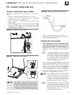
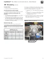


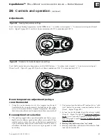

Figure 61
Thermostat or sensor wiring entrances
Part number 550-100-305/0118
50
AquaBalance
TM
W
ALL
M
OUNT
GAS
-
FIRED
WATER
BOILER
—
Boiler Manual
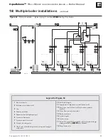
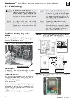
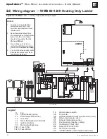
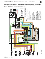
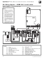
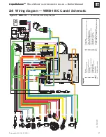
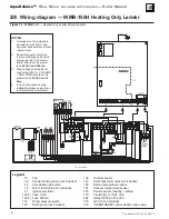
Combi and Heating Only boiler
wiring
The boiler is pre-wired and is ready to be plugged into your
electrical supply. Receptacle must be a grounded and polar-
ized circuit. Recommend GFI outlet.
21
Field wiring
ELECTRICAL SHOCK HAZARD
— For your
safety, turn off electrical power supply at service
entrance panel before making any electrical con-
nections to avoid possible electric shock hazard.
Failure to do so can cause severe personal injury
or death.
The installation must comply with: National
Electrical Code and any other national, state,
provincial or local codes or regulations. In
Canada, CSA C22.1 Canadian Electrical Code
Part 1, and any local codes.
Wiring must be N.E.C. Class 1. If original wir-
ing as supplied with boiler must be replaced,
use only type 105 °C wire or equivalent. Boiler
must be electrically grounded as required by
National Electrical Code ANSI/NFPA 70 – lat-
est edition
, and/or the Canadian Electrical Code
Part I, CSA C22.1, Electrical Code.
The boiler when installed, must be electri-
cally bonded to ground in accordance with the
requirements of the authority having jurisdiction
or, in the absence of such requirements, with the
National Electrical Code, ANSI/NFPA 70
– latest
edition
, and/or the Canadian Electrical Code
Part I, CSA C22.1, Electrical Code.
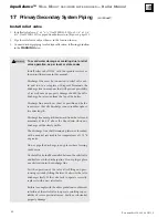
Wire entrances
All field wiring is made through the bottom of the boiler
through two (2) black grommets shown in Figure 61.
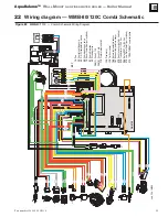
Connecting terminals
The electrical connections terminal block can be accessed
after removing the front jacket panel. The layout of the ter-
minals for the various connections are shown in the wiring
diagram in the following pages.
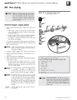
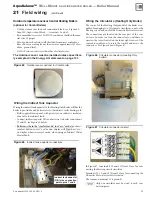
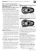
Room thermostat
When connecting a room thermostat, connect the thermo-
stat across terminals
R
and
W
for a two (2) -wire thermostat
or optional
R
,
W
and
C
for a three (3) -wire thermostat, see
Figure 62, Item 72. The thermostat connector is located on
the right side of the boiler.
Either a voltage free thermostat or a 24VAC
thermostat can be connected to the boiler.
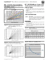
Figure 63
Thermostat-Relay box terminals Combi and Central
Heating boilers
Wire grommets
Figure 62
Thermostat terminals Combi and Central Heating
and Outdoor sensor (Heating Only Boilers)
See illustrations in the following pages for notes and
numbers.
Outside of
Thermostat-Relay
Box
Inside of
Thermostat-Relay
Box
Transformer
Relay
Fuse