29
4.3.3 MULTI-UNIT CONFIGURATION
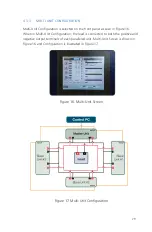
Multi-Unit Configuration is selected on the front panel as seen in Figure 16.
When in Multi-Unit Configuration, the load is connected to both the positive and
negative output terminals of each paralleled unit. Multi-Unit Screen is shown in
Figure 16 and Configuration is illustrated in Figure 17.
Figure 16. Multi-Unit Screen
Figure 17. Multi-Unit Configuration
Содержание 900EX
Страница 1: ...Installation Operation and Maintenance Manual EV Test Systems 900 EX ...
Страница 6: ...iv ...
Страница 7: ...Chapter 1 Introduction ...
Страница 11: ...Chapter 2 System Description ...
Страница 25: ...Chapter 3 Installation ...
Страница 29: ...Chapter 4 Operation ...
Страница 48: ...42 ...
Страница 49: ...Chapter 5 Maintenance ...
Страница 53: ...Appendix A Glossary of Terms ...
Страница 58: ...52 ...
Страница 59: ...Appendix B DC I O Connector Assembly ...
Страница 63: ...Appendix C 900 EX Remote Voltage Sense Operation ...
Страница 66: ...60 ...
Страница 67: ...Appendix D High Voltage Interlock Wiring ...
Страница 69: ...Appendix E Index ...
Страница 72: ...22855 03 04 ...

