12
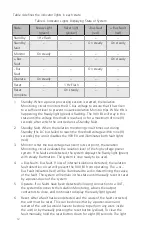
Table 4 defines the indicator lights in each state.
Table 4. Indicator Lights Displaying State of System
State
Ready Light
(green)
Reset light
(yellow)
-Bus Fault
(red)
+ Bus Fault
(red)
Standby
1 Hz Flash
–
–
–
Standby
fault
–
–
On steady
On steady
Monitor
On steady
–
–
–
+ Bus
Fault
–
–
–
On steady
- Bus
Fault
–
–
On steady
–
Operate
On steady
–
–
–
Reset
–
1 Hz Flash
–
–
Reset
complete
–
On steady
–
–
1. Standby. When a power processing session is started, the Isolation
Monitoring circuit monitors the DC bus voltage to ensure that it has risen
to a sufficient level to prevent nuisance Isolation Monitor trips. While this is
happening, the Ready light (green) is flashing. The 900 EX will stay in this
state until the voltage threshold is reached, or for a maximum of nine (9)
seconds, after which the unit declares a Standby Fault.
2. Standby Fault. When the Isolation monitoring circuit times out during
Standby (the DC bus failed to reach the threshold voltage within nine (9)
seconds), the circuit disables the 900 EX and illuminates both fault lights
(red).
3. Monitor. After the bus voltage has risen to its set point, the Isolation
Monitoring circuit evaluates the isolation level of the high voltage power
system. If no faults are detected, the system displays the Ready light (green)
with steady illumination. The system is now ready to be used.
4. + Bus Fault/- Bus Fault. If loss of internal isolation is detected, the isolation
fault detection circuit will prevent the 900 EX from operating. The + or –
Bus Fault indicators (red) will be illuminated to aid in determining the cause
of the fault. The system will remain in this state until manually reset or reset
by a power-down of the system.
5. Operate. If no faults have been detected following connection to a UUT,
the system disconnects the Isolation Monitoring, allows the output
contactors to close, and continues to display the ready light (green).
6. Reset. After a fault has been detected and the cause of the fault corrected,
the unit must be reset. This can be done either by a power-down and
restart of the unit (as would have to be done to perform any work inside
the unit) or by manually pressing the reset button (yellow). To clear the
fault manually, hold the reset button down for eight (8) seconds. The light
Содержание 900EX
Страница 1: ...Installation Operation and Maintenance Manual EV Test Systems 900 EX ...
Страница 6: ...iv ...
Страница 7: ...Chapter 1 Introduction ...
Страница 11: ...Chapter 2 System Description ...
Страница 25: ...Chapter 3 Installation ...
Страница 29: ...Chapter 4 Operation ...
Страница 48: ...42 ...
Страница 49: ...Chapter 5 Maintenance ...
Страница 53: ...Appendix A Glossary of Terms ...
Страница 58: ...52 ...
Страница 59: ...Appendix B DC I O Connector Assembly ...
Страница 63: ...Appendix C 900 EX Remote Voltage Sense Operation ...
Страница 66: ...60 ...
Страница 67: ...Appendix D High Voltage Interlock Wiring ...
Страница 69: ...Appendix E Index ...
Страница 72: ...22855 03 04 ...


