55
The simple and easy procedure for assembly or
disassembly offers the flexibility to change or replace
contacts and/or insulator sleeves in the field as well as
easily reuse component parts
B.2 NO CAMLOCKS UNIT
B.2.1 EQUIPMENT REQUIREMENTS
Flexible cable 350MCM, 1000Vac rated to connect to the 500A load.
B.2.2 GENERAL
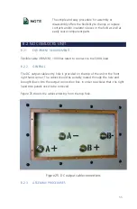
The DC output cable entry hole is provided on the top of the unit in the front
right hand corner. The cables should be suitably routed through the hole and
brought down into the output connection box. In order to achieve that, the right
hand side panels need to be removed.
Figure 25 shows the cables entering from the top hole.
Figure 25. DC output cable connections
B.2.3 ASSEMBLY PROCEDURES
Содержание 900EX
Страница 1: ...Installation Operation and Maintenance Manual EV Test Systems 900 EX ...
Страница 6: ...iv ...
Страница 7: ...Chapter 1 Introduction ...
Страница 11: ...Chapter 2 System Description ...
Страница 25: ...Chapter 3 Installation ...
Страница 29: ...Chapter 4 Operation ...
Страница 48: ...42 ...
Страница 49: ...Chapter 5 Maintenance ...
Страница 53: ...Appendix A Glossary of Terms ...
Страница 58: ...52 ...
Страница 59: ...Appendix B DC I O Connector Assembly ...
Страница 63: ...Appendix C 900 EX Remote Voltage Sense Operation ...
Страница 66: ...60 ...
Страница 67: ...Appendix D High Voltage Interlock Wiring ...
Страница 69: ...Appendix E Index ...
Страница 72: ...22855 03 04 ...


