26
Part No. 920559 Rev H
November 2008
3.6 Blend Ratio Setting,
continued
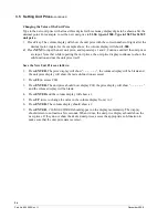
Saving the New Blend Ratio
1. Press
ENTER.
The price display will show “–
– – – – –
“, the volume display will be blank and the unit
price display will show the last sub-function accessed.
2. Press
00
(to access F00)
3. Press
ENTER.
The unit price should now display
F00
, the price display will show “–
– – – – –
“
and the volume display will be blank.
4. Press
ENTER
and the volume display will show a
1
.
5. Press
UP
twice to change the value in the volume display from
1
to
3.
6. Press
ENTER.
The volume display should show a
3
.
7. Press
ENTER.
CHANGE STORED
should appear on the display momentarily. The display should
return to normal in a few seconds. When it does, the unit price displays should show the new prices. If
they do not show the desired unit prices, access the appropriate sub-function to make sure that the unit
price data is correct.
For reference, the following is a 50% blend ratio setting for a single hose blender, Ovation model B12/3 xxxx,
as listed in Table 3-1. Any unused position has to be set to 101 not 0.
Side 1
Side 2
18.11 = 101
18.21 = 101
18.12 = 101
18.22 = 101
18.13 = 100
Super (Hi Feedstock)
18.23 = 100
18.14 = 101
18.24 = 101
18.15 = 50
Plus (Blend BL)
18.25 = 50
18.16 = 101
18.26 = 101
18.17 = 0
Regular(Lo Feedstock)
18.27 = 0
Typically, stations sell the low and high grades at zero and 100 percent ratios and may sell the middle grade
at 35 percent or some other intermediate value between 0 and 100. On the above model, the technician
would need to change only sub-functions 18.15 and 18.25 to the intermediate value.
As a reminder, always get the blend ratios from the station owner to avoid any confusion over which values
to use.
Содержание Ovation
Страница 1: ...INSTALLATION Ovation Dispensers OPERATION...
Страница 3: ...November 2008 Part No 920559 Rev H Ovation Series Dispensers Installation Operation...
Страница 4: ...November 2008 Part No 920559 Rev H...
Страница 54: ...48 Part No 920559 Rev H November 2008...
Страница 66: ...60 Part No 920559 Rev H November 2008...
Страница 67: ...61 November 2008 Part No 920559 Rev H DISTANCE BETWEEN EYE BOLTS 33 1...
Страница 68: ...62 Part No 920559 Rev H November 2008 INSTALLATION INSTRUCTION page 1 of 2 OVATION MODEL R13...
Страница 69: ...63 November 2008 Part No 920559 Rev H INSTALLATION INSTRUCTION page 2 of 2 OVATION MODEL R13...
Страница 70: ...64 Part No 920559 Rev H November 2008 INSTALLATION INSTRUCTION page 1 of 2 OVATION MODEL B23...
Страница 71: ...65 November 2008 Part No 920559 Rev H INSTALLATION INSTRUCTION page 2 of 2 OVATION MODEL B23...
Страница 72: ...66 Part No 920559 Rev H November 2008 INSTALLATION INSTRUCTION page 1 of 2 OVATION MODELS B12 AND R22...
Страница 73: ...67 November 2008 Part No 920559 Rev H INSTALLATION INSTRUCTION page 2 of 2 OVATION MODELS B12 AND R22...
Страница 74: ...68 Part No 920559 Rev H November 2008 INSTALLATION INSTRUCTION page 1 of 2 OVATION MODEL R11...
Страница 75: ...69 November 2008 Part No 920559 Rev H INSTALLATION INSTRUCTION page 2 of 2 OVATION MODEL R11...
Страница 76: ...70 November 2008 Part No 920559 Rev H...
Страница 77: ...71 November 2008 Part No 920559 Rev H 2 7151 C TYPICAL SITE WIRING...
Страница 78: ...72 Part No 920559 Rev H November 2008...
Страница 80: ...74 Part No 920559 Rev H November 2008...
Страница 81: ...75 November 2008 Part No 920559 Rev H APPENDIX D SITE INTERCONNECTION DIAGRAMS...
Страница 82: ...76 Part No 920559 Rev H November 2008 Figure D 1 Backroom Installation Wayne Control System...
Страница 84: ...78 Part No 920559 Rev H November 2008 Figure D 3 Pump Relay Installation Wiring Diagram...


