9
November 2008
Part No. 920559 Rev H
WARNING
Electric Shock Hazard! No connections (including neutral) may be shared between groups of dispensers.
A separate Control Power Circuit Breaker must be provided for each group. Failure to do so may result in
serious injury.
2.6.3 Field Wiring for Dispensers Without a Junction Box
All field wiring must enter the Electronic Head via
potted conduit/conduit fittings
. When a dispenser
does not contain a junction box, the conduits must be potted in the field during dispenser installation.
Note:
This also applies to the secondary conduit containing the Ethernet cable and the intercom call button/
speaker wires even if the dispenser does have a junction box since these wires do not connect in the junction
box.
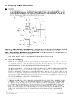
1. Install (2) 3/4” field conduits from the UL approved seal-offs at the base of the dispenser to the conduit at
the vapor barrier as identified in Figure 2-5. One conduit will contain, as applicable, the Ethernet cable
and the intercom (call button and speaker) wires (low voltage - Class 2 circuits). The other conduit will
contain the pump power, relay selects, valance lighting and data wires (Power - Class 1 circuits).
2. Clean conduit threads before connecting.
3. Pull continuous uninterrupted lengths of wires from the station electrical panels and control boxes to the
dispenser electronic head. Allow an extra 18” lengths past the vapor barrier fitting for terminating,
separating, potting and connecting to the terminal block. If installing iX CAT or IDPOS dispensers, allow
an extra 3 ft. of Ethernet cable past the top of the conduit in the vapor barrier.
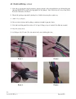
4. From each conduit, separate the wires using 3-201623 Wire Separator Gasket. See Photo 1.
5. Roll separator gasket and wires into a cylinder and secure with electrical tape. Photo 2 and Photo 3.
6. Pull separator gasket and wires back through the conduit fitting (Photo 4) forming a dam in the conduit,
with the top of the separator down in the conduit past the dimple in the conduit.
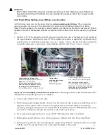
Figure 2-5 Terminal Block Inside Electronic Enclosure.
Field wiring connects to this terminal block when
the junction box shown in Figure 2-4 is not installed.
intercom speaker wires (Brown pair)
Potted Fitting contains Pump Power,
,
Potted conduit for Ethernet and
Terminal Block
used when junction box
Intercom Call Button/speaker wires only.
is not installed.
MGD Wiring Shown.
Note:
With or without j-box,
Note: Main potted fitting contains
Data, Relay Selects, Valance lighting
this conduit now goes directly to the
seal offs under the dispenser to allow
for a straight run of Ethernet cable
from building switch to dispenser switch.
conduit along with the call button wires.
These must run in separate underground
See optional equipment section.
Содержание Ovation
Страница 1: ...INSTALLATION Ovation Dispensers OPERATION...
Страница 3: ...November 2008 Part No 920559 Rev H Ovation Series Dispensers Installation Operation...
Страница 4: ...November 2008 Part No 920559 Rev H...
Страница 54: ...48 Part No 920559 Rev H November 2008...
Страница 66: ...60 Part No 920559 Rev H November 2008...
Страница 67: ...61 November 2008 Part No 920559 Rev H DISTANCE BETWEEN EYE BOLTS 33 1...
Страница 68: ...62 Part No 920559 Rev H November 2008 INSTALLATION INSTRUCTION page 1 of 2 OVATION MODEL R13...
Страница 69: ...63 November 2008 Part No 920559 Rev H INSTALLATION INSTRUCTION page 2 of 2 OVATION MODEL R13...
Страница 70: ...64 Part No 920559 Rev H November 2008 INSTALLATION INSTRUCTION page 1 of 2 OVATION MODEL B23...
Страница 71: ...65 November 2008 Part No 920559 Rev H INSTALLATION INSTRUCTION page 2 of 2 OVATION MODEL B23...
Страница 72: ...66 Part No 920559 Rev H November 2008 INSTALLATION INSTRUCTION page 1 of 2 OVATION MODELS B12 AND R22...
Страница 73: ...67 November 2008 Part No 920559 Rev H INSTALLATION INSTRUCTION page 2 of 2 OVATION MODELS B12 AND R22...
Страница 74: ...68 Part No 920559 Rev H November 2008 INSTALLATION INSTRUCTION page 1 of 2 OVATION MODEL R11...
Страница 75: ...69 November 2008 Part No 920559 Rev H INSTALLATION INSTRUCTION page 2 of 2 OVATION MODEL R11...
Страница 76: ...70 November 2008 Part No 920559 Rev H...
Страница 77: ...71 November 2008 Part No 920559 Rev H 2 7151 C TYPICAL SITE WIRING...
Страница 78: ...72 Part No 920559 Rev H November 2008...
Страница 80: ...74 Part No 920559 Rev H November 2008...
Страница 81: ...75 November 2008 Part No 920559 Rev H APPENDIX D SITE INTERCONNECTION DIAGRAMS...
Страница 82: ...76 Part No 920559 Rev H November 2008 Figure D 1 Backroom Installation Wayne Control System...
Страница 84: ...78 Part No 920559 Rev H November 2008 Figure D 3 Pump Relay Installation Wiring Diagram...


