25
November 2008
Part No. 920559 Rev H
3.6 Setting Blend Ratios
The procedure below is used to set the dispenser blend ratios. When enabled, the POS system verifies and
confirms that its blend ratio data corresponds to the manually set blend ratios. The Wayne POS system will
not allow fuel to be dispensed if these numbers do not match.
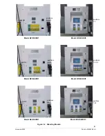
The pump computer recognizes code stored in memory that defines a dispenser model and assigns logical
nozzle numbers to the hose positions as explained in Section 3.3. Once this is done, the function
F18
is
accessed to set the blend ratios, using the remote control interface. The sub-function
F18.1N,
where
N
is the
logical nozzle number, is used to set the blend ratios for side 1 and the sub-function
F18.2N
is used to set
the blend ratios for side 2. Active values of
N
are given in Table 3-1.
To set the blend ratio, the correct sub-function is accessed, the blend ratio is changed to its new value and
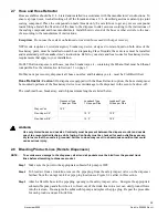
the data is saved. To access the desired sub-function, the following steps must be performed using the
remote control (
Bold
type denote remote control function and
italicized
type represents dispenser response):
NOTE: BLEND RATIOS MUST BE SET FOR SIDE 1 AND AGAIN FOR SIDE 2.
To access the Blend Ratio sub-function:
1. Press
ENTER
PASS 1
(enter password)
2. Press
ENTER
PASS 2
(enter password)
3. Press
ENTER.
The unit price display will show
F—
(indicating that it needs a function number to pro-
ceed)
4. Press
18
to access
F18
5. Press
ENTER.
The unit price display will show
F18
(indicating that the function has been accessed)
6. Press
ENTER
to access the sub-functions of
F18.
The unit price display will show
18.11
(here
N=1
)
The volume display will indicate the value of the blend ratio corresponding to logical nozzle #1(
N=1
). If
there is no data for this logical nozzle, the number “
101
” will be displayed. This applies to all logical noz-
zles. To access the blend ratio for the next logical nozzle, press
NEXT
. The unit price display will show
18.12
and the volume display will show whatever the value of the blend ratio is for logical nozzle #2. Suc-
cessive presses of
NEXT
will advance the unit price display to
18.17
, the last logical nozzle. Pressing
NEXT
again will advance the unit price display to
18.21
, The “
2
” in “
18.21
” indicates Side 2 and the “
1
”,
logical nozzle #1. The volume display will show the blend ratio assigned to
logical nozzle #1 of Side 2
.
Changing the Value of the Blend Ratio
1. When the desired logical nozzle is shown on the unit price display, enter the desired value of the blend
ratio by using
UP
and
DOWN
keys on the remote control interface or by typing the
#
sign followed by
the value of the blend ratio, followed by
ENTER
. For example, to change the value of the blend ratio
from
101
to
89
, press the
DOWN
button until
89
shows up on the price display, then press
ENTER
, or
type in
#89, ENTER.
2. Continue until all the blend ratios are entered for side 1.
3. Repeat for side 2 and save as follows:
Содержание Ovation
Страница 1: ...INSTALLATION Ovation Dispensers OPERATION...
Страница 3: ...November 2008 Part No 920559 Rev H Ovation Series Dispensers Installation Operation...
Страница 4: ...November 2008 Part No 920559 Rev H...
Страница 54: ...48 Part No 920559 Rev H November 2008...
Страница 66: ...60 Part No 920559 Rev H November 2008...
Страница 67: ...61 November 2008 Part No 920559 Rev H DISTANCE BETWEEN EYE BOLTS 33 1...
Страница 68: ...62 Part No 920559 Rev H November 2008 INSTALLATION INSTRUCTION page 1 of 2 OVATION MODEL R13...
Страница 69: ...63 November 2008 Part No 920559 Rev H INSTALLATION INSTRUCTION page 2 of 2 OVATION MODEL R13...
Страница 70: ...64 Part No 920559 Rev H November 2008 INSTALLATION INSTRUCTION page 1 of 2 OVATION MODEL B23...
Страница 71: ...65 November 2008 Part No 920559 Rev H INSTALLATION INSTRUCTION page 2 of 2 OVATION MODEL B23...
Страница 72: ...66 Part No 920559 Rev H November 2008 INSTALLATION INSTRUCTION page 1 of 2 OVATION MODELS B12 AND R22...
Страница 73: ...67 November 2008 Part No 920559 Rev H INSTALLATION INSTRUCTION page 2 of 2 OVATION MODELS B12 AND R22...
Страница 74: ...68 Part No 920559 Rev H November 2008 INSTALLATION INSTRUCTION page 1 of 2 OVATION MODEL R11...
Страница 75: ...69 November 2008 Part No 920559 Rev H INSTALLATION INSTRUCTION page 2 of 2 OVATION MODEL R11...
Страница 76: ...70 November 2008 Part No 920559 Rev H...
Страница 77: ...71 November 2008 Part No 920559 Rev H 2 7151 C TYPICAL SITE WIRING...
Страница 78: ...72 Part No 920559 Rev H November 2008...
Страница 80: ...74 Part No 920559 Rev H November 2008...
Страница 81: ...75 November 2008 Part No 920559 Rev H APPENDIX D SITE INTERCONNECTION DIAGRAMS...
Страница 82: ...76 Part No 920559 Rev H November 2008 Figure D 1 Backroom Installation Wayne Control System...
Страница 84: ...78 Part No 920559 Rev H November 2008 Figure D 3 Pump Relay Installation Wiring Diagram...


