82
CHAPTER 9
•
CLICK 110
Push-buttons
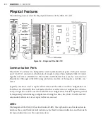
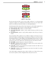
The faceplate of the Click 110 features two push-buttons. The upper push-button, labeled
Mode Switch, is used to cycle through and select menu and configuration options.
The lower push-button, labeled Reset, will reboot the Click 110. The Click 110 can be re-
booted in any of three ways: via the reset switch, from the outstation via the 64 way DIN
41612, or by power cycling the device. A reboot is the only way to clear a latched fault con-
dition. To reboot using the reset switch, simply press and release the push-button.
DIP Switches
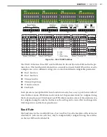
Just behind the faceplate of the Click 110, on the circuit board, is a set of DIP switches.
These switches are used to configure the Click 110 in Hardware mode. All settings, with
the exception of Outstation mode and disabling fault latching, are also configurable via
Software mode (front panel menu, or Click Supervisor). See the DIP Switches section of
this chapter for more information.
Installation and Wiring
Use the following steps to install and wire Click 110 devices:
1
If you’re using hardware configuration, set all DIP switches before installing Click 110
devices (this will be covered in the DIP Switches section of this chapter).
2
Insert the cards into the rack.
3
Daisy-chain together all the cards you intend to use in your installation, using short
RJ-11 jumper cables.
4
Connect the first Click 110 card to the SmartSensor via a surge protector, such as the
Click 200, 222, or 223, and a 60" RJ-11 patch cord.
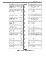
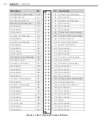
For your information, this guide includes the pinout for the 64-pin backplane connector
on the the back of the Click 110. However, the pins behave differently depending on which
Outstation mode the device is set to, Peek or Siemens (for more on Outstation mode, see
the DIP Switches section of this chapter); the differences all relate to the fault outputs and
whether they are normally opened or normally closed.
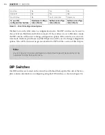
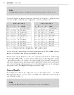
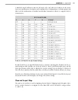
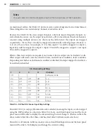
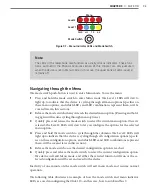
For this reason, there are two pinout tables on the following pages. The first is the pinout
when the Click 110 is set to Peek; the second is when it’s set to Siemens.
Note
The pins that change between the two tables will be highlighted in light gray for ease
of comparison.
Содержание Click 100
Страница 1: ...Click 100 400 Series USER GUIDE...
Страница 2: ...Click 100 400 Series USER GUIDE www wavetronix com 78 East 1700 South Provo Utah 84606 801 734 7200...
Страница 11: ......
Страница 17: ......
Страница 27: ......
Страница 41: ......
Страница 43: ......
Страница 79: ......
Страница 129: ......
Страница 145: ......
Страница 161: ......
Страница 175: ......
Страница 183: ......
Страница 187: ......
Страница 207: ......
Страница 219: ......
Страница 225: ......
Страница 245: ......
Страница 259: ......
Страница 260: ...www wavetronix com...


