228
CHAPTER 27
•
CLICK 340/341/342
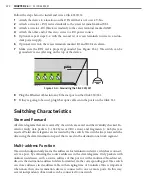
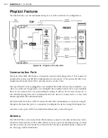
meaning that power and communications will have to be wired in. Follow the steps below
to install and wire a Click 340, 341 or 342:
1
Attach the device to a location on the DIN rail.
2
Attach a wire for +DC (red is standard) to the screw terminal marked US1.
3
Attach a wire for -DC (black is standard) to the screw terminal marked GND.
4
Attach the other end of these two wires to a DC power source. In a traffic installation
with other Click modules, the best way to do this is to attach a female 5-screw terminal
block to the end of the T-bus and wire the +DC and -DC from step 2 into the top two
terminal connectors.
5
Make sure the DIN rail is properly grounded, as the devices are grounded via a foot
that connects with the DIN rail.
Содержание Click 100
Страница 1: ...Click 100 400 Series USER GUIDE...
Страница 2: ...Click 100 400 Series USER GUIDE www wavetronix com 78 East 1700 South Provo Utah 84606 801 734 7200...
Страница 11: ......
Страница 17: ......
Страница 27: ......
Страница 41: ......
Страница 43: ......
Страница 79: ......
Страница 129: ......
Страница 145: ......
Страница 161: ......
Страница 175: ......
Страница 183: ......
Страница 187: ......
Страница 207: ......
Страница 219: ......
Страница 225: ......
Страница 245: ......
Страница 259: ......
Страница 260: ...www wavetronix com...


