background image

7


Installation Procedure

- Water Supply Connection and Bypass Valve -

To allow for filter servicing, swimming pool filling or lawn sprinkling, a manual Bypass Valve has been in-

stalled at the 

factory. The Bypass allows raw water to be manually routed around the filter.

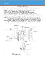
1. Position filter at desired location for installation. If a water softener is to be installed, the filter should be

    positioned first and then the softener. (See Installation Diagrams.)

2. The filter media is shipped separately from the mineral tank. The tank must be loaded with media after 

    tank has been placed at the desired location.


A. Remove the tank closure by unscrewing from the tank.


B. Use cap provided to place over top of distributor tube to prevent media from entering tube while 

                  filling.


C. Place media funnel in hole on top of tank.


D. Pour several gallons of water in the tank. (Fill tank about 1/3 full.)


E. Pour in the required filter media. Gravel underbedding has been installed at the factory. The  


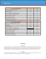
    required quantity & type of media is listed in the filter specifications on page 4.


Note

: The order in which the media buckets gets poured into the tank does not matter. 


F. After installing filter media, add the included pack of aeration balls or KDF cubes.


G. After filling the tank with material, use a garden hose or several buckets to fill the tank with wa   


     ter.


Note: 

This will permit the filtering media to become soaked while preparing the installation and will  


           prevent the control valve from being plugged with floating media on initial backwash.


H. Remove funnel and clean filter media from tank threads.


 I.  Remove cap from distributor tube.


 J.  Replace tank closure on mineral tank.


3. Turn OFF main water supply and OPEN nearest faucet to relieve pressure.

4. Cut main line and install appropriate elbows and extensions. 

Caution: 

Raised arrows located on the sides of control valve body and bypass valve indicate proper direc   

                 tion of water flow. Install inlet and outlet piping in direction of arrows. It is recommended that a 


   vacuum breaker be installed on the inlet plumbing.

- Drain Line Connection -

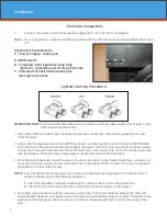
1. The drain line flow control assembly is pre-assembled for your convenience. Should you choose to hard 

    plumb the drain line, please remove the barb fitting. The flow control housing can be removed by remov

    ing the clip and pulling straight out on housing. 

Note:

 When re-installing the drain line flow control housing, be sure you hear and feel the O-Ring pop into 

            place before inserting the clip.

2. Install 1/2” I.D. drain line tubing (not included) from hose barb to an open drain. A 4” gap between end of 

    the drain line and the open drain is required to prevent waste water backflow. Keep the drain line as 

    short as possible. An overhead drain line can be used if necessary, but should discharge below the con

    trol valve. A syphon trap (taped loop) at the outlet of the drain line is advisable to keep the drain line full       

    and assure correct flow during backwash. Elbows or other fittings must be kept at a bare minimum.

Note:

 Where the drain line is elevated above the control valve or exceeds 20 feet in length, 3/4” I.D. drain 

            line tubing should be used. 

Installation

Содержание SIDEWINDR SW10

Страница 1: ...Installation Operation Manual...

Страница 2: ...ke from a few seconds to a minute depending on the amount of oxygen and the pressure This noticeable side effect tells you the system is working properly and also will actually enhance the palatabilit...

Страница 3: ...quirements Page 6 Set Up Utilizing Bluetooth App Page 10 Set Up Using Buttons and Display on Valve Page 13 Master Programming Page 16 Control Valve Power Assembly Page 17 Valve Body Assembly Page 19 T...

Страница 4: ...l plastic Noryl threaded fittings Specifications General Specifications SW10 SW13 Smart Blend Media Capacity cu ft 1 5 cu ft 2 5 cu ft Mineral Tank Size 10 x 54 13 x 54 Service Flow Rate Continuous gp...

Страница 5: ...loosely Use caution with lubricated O rings 2 Attach the mounting screw in the bottom before completely tightening the plumbing connections 3 Attach air intake tubing to push lock elbow on side of con...

Страница 6: ...obtain di electric unions to prevent dissimilar metal corrosion Note Where the drain line is elevated above the control valve or exceeds 20 feet in length to reach the drain use 3 4 I D drain line tu...

Страница 7: ...m being plugged with floating media on initial backwash H Remove funnel and clean filter media from tank threads I Remove cap from distributor tube J Replace tank closure on mineral tank 3 Turn OFF ma...

Страница 8: ...runs clear close the tap NOTE Any time media other than very fine mineral on initial startup is apparent in the service lines it usually indicates one of the following problems A The unit is plumbed i...

Страница 9: ...in to REGISTER YOUR PRODUCT online at www watersoftinc com 4 Leave this manual with the homeowner Important Notice The plumbing system piping pressure tank hot water tanks softeners etc that have been...

Страница 10: ...the default password the first time you connect to it the app will ask you to enter the password After entering it the first time you should not need to enter it again unless it changes 3 BTLE Valve d...

Страница 11: ...s in ORANGE with a set button can be changed For Filters Set Backwash Frequency This sets the amount of day between backwash cycles Change Time of Day Press SET to set time automatically based on devi...

Страница 12: ...p Option 2 Touch any graph to enlarge and see details Enlarged graphs are able to be zoomed in by pinching with two fingers Enlarged graph shown below Regenerate Unit at Next Regen Time button This wi...

Страница 13: ...in at the set Backwash Time A 00 setting will cancel this feature The Max Value for this item is 29 Example Every 6 days A 06 Default Setting To Adjust this Value Press the Set Change Button To Accept...

Страница 14: ...where it left off prior to the power interruption When used without battery back up during a power failure the unit stops at its current point in the regeneration position and then restarts at that po...

Страница 15: ...after running water in the backwash step Note Depending upon system pressure and other factors it is possible to observe a small amount of flow to drain in the rest cycle Step 4 Air Replenish Default...

Страница 16: ...y screen The number of minutes allotted for the selected backwash step is displayed on the far right Change the digit values using the Set Change and Menu Enter buttons as described above Note on Air...

Страница 17: ...17 Control Valve Powerhead Assembly 3 4 5 6 7 8 10 11 15 14 13 18 17 12 16 E LETTERS IN DIAGRAM REPRESENT WIRING CONNECTIONS 1 E P M P P M 9 F F...

Страница 18: ...X125 1 7 Back Plate 20001X005 1 8 Lower Front Base For Cover 20111X002 1 9 Legacy View Motor Assy 20016X006 1 10 Lower Back Base For Cover 20111X003 1 11 Valve Cover 20111X000 1 12 6 32 X 5 16 Phillip...

Страница 19: ...19 Sidewindr Valve Body Assembly 2 8 1 3 19 20 27 14 15 AIR INJECTION ASSEMBLY Located near base of tank To Air Injection Assembly 4 21A 9 10 11 12 17 18 16 13 22 26 21B 25 24 23 5 7 6 6 6 6A...

Страница 20: ...0009X228 1 10 BLFC Ferrule 3 8 20251X305 1 11 Plug 3 8 20009X005 1 12 10 24 X 3 4 Screw SST 20001X226 2 13 3 8 Push Lock Plug 20009X010 1 14 Injector Cap 20009X001 1 15 Injector Seal 20001X224 1 16 In...

Страница 21: ...N A 5 20015X 6 33000X 7 20015X 8 20015X 9 20015X 20015X 10 GA Q06 11 57005X 12 GA R06 13 20017X 20018X 14 57005X 15 70000X 16 70000X 17 20015X 18 02105 19 20015X 20015X 20 20015X 21 20015X 22 20561X...

Страница 22: ...4 3 8 Brine Tubing per ft 57005X001 2 15 Bracket Retainer 70000X034 1 16 Sidekick Air Injection Bracket 70000X035 1 17 3 8 Push Lock Ball Valve 20015X022 1 18 Self Tapping Screw NA 2 19a 10 Sidekick M...

Страница 23: ...units 20017X284 3 1 Female Straight Slip Set optional 20017X288 4 1 NPT Straight Set optional 20017X289 5 3 4 NPT Straight Set optional 20017X307 6 1 X 3 4 Brass Sweat Connector Set optional 20017X304...

Страница 24: ...cover C To Replace Piston Assembly 1 Follow steps A1 A3 2 Disconnect the meter signal wire from the circuit board 3 Remove lower back base screws and detach lower back base 4 Remove screw and washer a...

Страница 25: ...at www watersoftinc com E To Replace Meter 1 Follow steps A1 A3 2 Unplug meter cable from front of circuit board 3 Unscrew meter assembly nut from valve body 4 Remove meter from valve body and clean o...

Страница 26: ...r Quality Check items listed in 1 and 2 Bypass valve open Close bypass valve Channeling Check for too slow or high service flow Check for media fouling Lack of aeration in water Program valve to draw...

Страница 27: ...ion If the encoder is plugged in and snapped into place skip to step 2 below If encoder is disconnected reconnect it and cycle power to clear the error 2 Disconnect powerhead from valve body cycle pow...

Страница 28: ...e following factors The electrical outlet is not powered or is switched off The power cable has come unplugged from the circuit board The power supply has come unplugged from your electrical outlet Th...

Страница 29: ...es service charges delivery expenses property damage administrative fees or any costs incurred by the purchaser in removing or reinstalling the water treatment equipment The Warranty does not cover an...

Страница 30: ...30...

Страница 31: ...31 710 Orange Street Ashland OH 44805 PH 419 289 1500 FAX 419 289 1515 www watersoftinc com 0423TV...

Отзывы: