background image

26

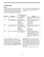
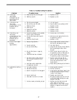
Table 6 - Troubleshooting Procedures

Problem

Possible Cause

Solution

1. Capacity display stays 

at 9999 even though 
there is water usage.

a. Total system capacity was 

calculated to be a value greater than 
9999.

a. As the water usage continues, the 

remaining capacity will drop below 
9999 and then other values will be 
shown.

2. Timer beeps when left 

arrow button is 
pressed.

a. Button is only active in the 

programming mode.

a. Refer to the Programming the Control 

section.

3. Timer does not 

respond to REGEN 
button.

a. Button is not active in the 

programming mode.

a. Refer to the Regeneration section.

4. Timer does not display 

time of day.

a. Transformer unplugged.

b. No electric power at outlet.

c. Defective transformer.

d. Defective circuit board.

a. Connect power.

b. Repair outlet or use working outlet.

c. Replace transformer.

d. Replace control.

5. Timer does not display 

correct time of day.

a. Outlet operated by a switch.

b. Power outages.

a. Use outlet not controlled by switch.

b. Reset Time of Day.

6. No water flow display 

when water is flowing 
(colon does not blink).

a. Bypass valve in bypass position.

b. Meter probe disconnected or not 

fully connected to meter housing.

c. Restricted meter turbine rotation 

due to foreign material in meter !

d. Defective meter probe.

e. Defective circuit board.

a. Shift bypass valve into service 

position.

b. Fully insert probe into meter housing.

c. Remove meter housing, free up turbine 

and flush with clean water. Turbine 
should spin freely. If not, refer to the 
Water Meter Maintenance section.

d. Replace control.

e. Replace control.

7. Control display is 

frozen at Regen Time 
Remaining.

a. Back to back regenerations were 

requested.

a. Refer to the Manual Regeneration 

section.

8. Control regenerates at 

the wrong time of day.

a. Power outages.

b. Time of day set incorrectly.

c. Time of regeneration set incorrectly.

a. Reset time of day to correct time of 

day.

b. Reset time of day to correct time of 

day.

c. Reset time of regeneration.

9. Timer stalled in 

regeneration cycle.

a. Motor not operating.

b. Motor runs backwards.

c. No electric power at outlet.

d. Incorrect voltage or frequency (Hz).

e. Broken gear.

f.

Defective switch.

g. Air leak in brine connections 

(pressure locked flapper).

h. Binding of camshaft.

i.

Water pressure greater than 
125 psi during regeneration.

j.

Defective circuit board.

a. Replace control.

b. Replace control.

c. Repair outlet or use working outlet.

d. Replace timer and/or transformer with 

one of correct voltage and frequency 
(Hz).

e. Replace control.

f.

Replace control.

g. Check all junction points and make 

appropriate corrections.

h. Remove foreign object obstruction 

from valve discs or camshaft.

i.

Install pressure regulator to reduce 
pressure.

j.

Replace control.

Содержание Series 255

Страница 1: ...Water Conditioning Control System Dealer Installation Operation and Maintenance Manual Series 255 Valve 960 Control...

Страница 2: ...on Service 14 Removing the Control Preventive Maintenance 15 Injector Screen and Injector Water Meter Disinfection of Water Conditioners 16 Sodium Hypochlorite 5 25 Calcium Hypochlorite Specifications...

Страница 3: ...ons include starting a regeneration only at a specific time of day or having an immediate regeneration when the capacity is exhausted The control can also have a fixed reserve which is a percentage of...

Страница 4: ...Five cycle operation provides for downflow conditioned water upflow backwash downflow brining and slow rinse downflow fast rinse and refill of the brine tank Valve discs are held closed by water press...

Страница 5: ...water heater Water heaters can transmit heat back down the cold water pipe into the control valve Hot water can severely damage the conditioner A 10 foot 3 m total pipe run including bends elbows etc...

Страница 6: ...into the tank and tighten with the plastic thumb nut and gasket as illustrated in Figure 6 3 Attach a length of 1 2 inch 1 3 cm tubing not supplied to the fitting and run to the drain Figure 6 Overflo...

Страница 7: ...the Control The control has default values for most parameters that were set at the factory but there are key items that need to be entered at the time of installation Time of Day Time of Regeneratio...

Страница 8: ...and the control accepts the new setting After approximately 30 seconds the control starts alternating the display between Time of Day and Capacity Note If a beep sounds the new setting is not accepted...

Страница 9: ...s Parameter Range of Values Minimum Increments Default Units of Measure Notes Name Description P1 Time of day AM or PM 1 00 to 12 59 00 00 to 23 59 1 None Hour minute Range depends on value selected f...

Страница 10: ...and the far right number on the display starts flashing If you want to change this number press the up arrow button or the down arrow button To skip the number without changing press the left arrow bu...

Страница 11: ...er for a 12 hour clock or enter 1 for a 24 hour clock P14 Calendar override 0 to 30 1 0 Days 0 no calendar override Skip this parameter for no calendar override or enter a value P15 Reserve type 0 to...

Страница 12: ...e two settings can only be viewed when the control is in the Level II mode The settings will be skipped when the control is in the Level I mode When Parameter 18 is set to zero the Salt Amount and Cap...

Страница 13: ...options for this control fixed reserve and historical water usage pattern They are selected with Parameter P15 Fixed reserve When the fixed reserve is selected the control multiplies the maximum syste...

Страница 14: ...g straight up This occurs when the indicator knob is rotated to the refill position Press down on the back of the camshaft to disengage it from the rear hoop of the top plate Figure 12 Slide the camsh...

Страница 15: ...crew and remove the injector screen and injector cap 5 Clean screen with a fine brush Flush with water until clean 6 Using a needle nose pliers pull the injector straight out 7 Flush water into the in...

Страница 16: ...to treat potable water In addition a conditioner can become fouled with organic matter during normal usage or with bacteria from the water supply Periodic disinfection is recommended for all condition...

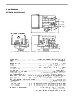
Страница 17: ...let outlet 3 8 inch BSPT drain 1 inch BSPT inlet outlet 1 2 inch BSPT drain Optional Bypass Valve 3 4 inch 19 1 mm or 1 inch 25 4 mm copper tailpiece 1 2 inch NPT male drain Valve Module Tank Adapter...

Страница 18: ...18 Pressure Graphs Tested with 3 4 inch Brass Manifold Bar Bar Bar...

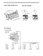
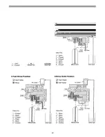
Страница 19: ...19 Control Valving Identification Flow Diagrams Brine 1 Inlet 2 Bypass 4 Outlet 3 Rinse Drain 5 Backwash Drain 6 Valve Disc Operation...

Страница 20: ...20...

Страница 21: ......

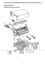
Страница 22: ...Ring 3 4 x 1 x 1 8 EP 1 6 Drain Control Assembly with O Rings 1 14 1031402 Locking Bar English Language 1 1034162 No 6 for 6 inch Diameter Tank 15 1006093 Screw No 8 x 9 16 inch 1 1000209 No 7 for 7 i...

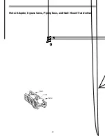
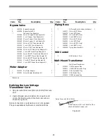
Страница 23: ...23 Meter Adapter Bypass Valve Piping Boss and Wall Mount Transformer Inlet Outlet Drain...

Страница 24: ...1 1040280 1 inch NPT Noryl 1001613 3 4 inch CPVC Tube Adapter Kit 1 1040283 3 4 inch BSPT Noryl 1001614 1 inch CPVC Tube Adapter Kit 1 1040284 1 inch BSPT Noryl 1001615 25 mm CPVC Tube Adapter Kit 1 2...

Страница 25: ...ve bypass into the bypass position and open the backwash drain valve the sixth valve back from the control with a screwdriver see Figure 11 Restore system water pressure when the service work is compl...

Страница 26: ...e meter probe e Defective circuit board a Shift bypass valve into service position b Fully insert probe into meter housing c Remove meter housing free up turbine and flush with clean water Turbine sho...

Страница 27: ...ased f Restricted meter turbine rotation due to foreign material in meter housing g Excessive water usage below 1 5 gallon per minute a Repeat regeneration making certain that correct salt dosage is u...

Страница 28: ...Replace both injector and injector cap 18 No conditioned water after regeneration a Unit did not regenerate b No salt in brine tank c Plugged injector d Air check valve closed prematurely a Check for...

Отзывы: