10
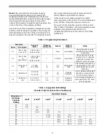
Level II Parameters (Table 3)
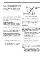
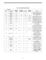
The Level II Parameters are P6 through P19 in Table 3.
The Operation and Maintenance Manual for this
product does not mention these parameters, so the
end user does not normally have access to these
values. To access Level II Parameters, simultaneously
press and hold the down arrow (
↓
) and up arrow (
↑
)
buttons for three seconds.
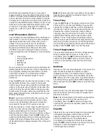
If the control was alternating between Time of Day and
Capacity when the above button sequence is entered,
the display shows P1. If a different Level I Parameter
was displayed, the display shows the “P” number for
that parameter. Refer to Table 3 to find the “P” number
associated with each parameter. Use the up arrow (
↑
)
button or the down arrow (
↓
) button to move from one
parameter to the next. The display cycles through the
“P” numbers shown in Tables 1 and 3. When you reach
P19, the next P number will go back to P1.
When the parameter number you want to change is on
the display, press the left arrow (
←
) button to display
the data assigned to that parameter. Press the SET
button and the far right number on the display starts
flashing. If you want to change this number, press the
up arrow (
↑
) button or the down arrow (
↓
) button. To
skip the number without changing, press the left arrow
(
←
) button. When the number is correct, press the SET
button. The numbers stop flashing and the control
accepts the new setting. If a beep sounds, the new
setting was not accepted. Refer to Table 3 for allowable
values for that parameter.
To change or view other parameters, press the left
arrow (
←
) button to have the display show “P”
numbers. Now use the up arrow (
↑
) button or the down
arrow (
↓
) button to move to the parameter number you
wish to change.
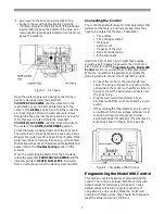
To exit the Level II programming mode, simultaneously
press and hold the down arrow (
↓
) and up arrow (
↑
)
buttons for three seconds, or wait 30 seconds without
pressing a button. The control starts alternating the
display between Time of Day and Capacity.
Settings for all parameters can be written on the label
provided with the control. The label has an adhesive
backing so it can be attached to the inside rear cover
for future service referenc-11( C6(.)]TJı/F13 1 Tfı˝02 00 ˝023-15004654.906 mDı˝0 Tcı˝-0.018 Twı˝[Spe(ci89(a)63(l)8( )-0(No(t)-8e(s f)-7(o11( Le)-7(e14(vl( )-0(Ie)5In)-5( )-0(Pt)7(a)63ra(mefer-9(.)]TJı/FF7 1 Tfı9.906 00 9.9063-15004637.326 mDı˝0.005 Tcı˝-0.606 Twı˝[T h)7e( )12((r)25(o)3(gr(amm)-10(n)15(g)13(pi89(a03ra(m )12(t)25(e)12ras )12iwn)7(Lh)7ea03vs)11(e)0l)-10l II-11((c-11(a03wn)7(bh)8(e10lfu)7(s)-5(e)12d.)-4( )12(t)25oe)13( )]TJı˝T*ı˝-0.007 Twı˝[(i)11(n)-4cr)13(r)26(e(s)12(( th)8( lef37(ficr)13is)-5(in)8cye)12(of( t)8(h)-4(i)11(s)0r co)14ned)9 it)8(i)11(o)2nt)8(e)1(r)109(.)7(E(sp)9(c(i)11 al)11(ye)12( )]TJı˝T*ı˝-0.003 Tcı˝0.002 Twı˝[noe)-7(te)87( th)-13(e )-12Re f)-8(i)2(l)-10l)12( )-12C(o)-7(ntr)17(o)-7(l)2(l)-10ear anre rwV ale-80( )]TJı˝T*ı˝0.005 Tcı˝-0.006 Twı˝[(p)8(a03rae)12(met)7ea03rs.rT hs wfere10( m )12( a )12(t)25( t)7(h)7ea03 fa(c-11tfo)13(y( t)7(o11 memet)7( t)7(h)-5(e)12( )]TJı˝T*ı˝0.045 Tcı˝[nr)6e(ed)7((of))11( sys)-10tr wl wtrpi-7(r245(ess)10us)67(r245())11.eIs an62( )]TJı˝T*ı˝-0.043 Tcı˝0.023 Twı˝[inhsthalplanhlahipre-80(wla)90tea(pr),wuselaa13(r)81(g)86es
inc(t)8(pr)or( do)14e(sndo)14tlfu81(s)0(( th)8( ed)9efafu81al)11tw(r)26(f(i)11al)11(s)-5(cont)8twr
hee fiiinof th sye c beimspr b
chigrPr Pr.
εντολ ς(α)5λυε.
Содержание Series 255
Страница 18: ...18 Pressure Graphs Tested with 3 4 inch Brass Manifold Bar Bar Bar...
Страница 20: ...20...
Страница 21: ......
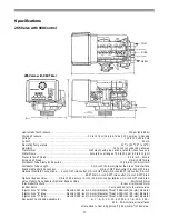
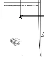
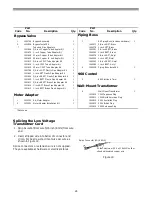
Страница 23: ...23 Meter Adapter Bypass Valve Piping Boss and Wall Mount Transformer Inlet Outlet Drain...


