background image

20

6.  Operating the device 

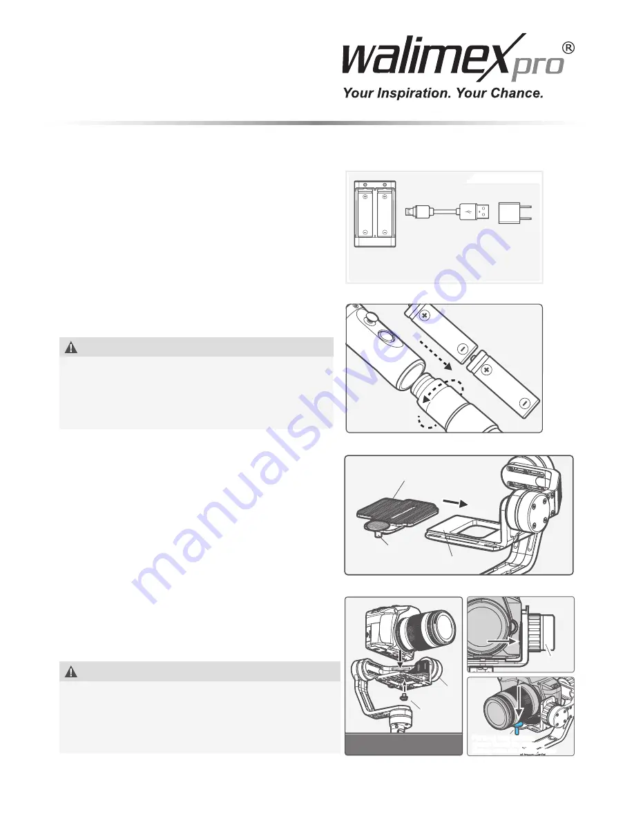
6.1 Charging / inserting the powerpack 

Only use for charger supplied for charging the batte-

ries. Insert the batteries into the charger. Ensure cor-

rect polarity. Use the micro USB cable to connect the 

charger to your computer or to a 5V USB power supply 

unit (optional), for mobile telephone, for example. The 

charging will then start. It will take between 2 and 4 

hours for charging to complete.
Unscrew the handle from the gimbal. Insert the 18650-

type batteries into the charger. Ensure correct polarity. 

Screw the handle back on to the gimbal.


Note

Use only 18650-type batteries. Ensure correct polarity 

when inserting the batteries. Strictly follow all notes 

on safety in these instructions for use. Precautionary 

measures when using batteries. - Use only the power 

supply unit delivered with the device.

6.2  Mounting the camera 

Slide the quick-release plate on to the mounting 

surface of the gimbal. Move the lens fi xation screw 

into the desired position. Then attach it with the screws 

provided. 

6.3  Securing the camera 

Assemble the camera on to the quick-release plate. 

Fix and secure it with the fi xation screw. The camera 

should be near the motor for the tilt axis. The camera 

should be positioned with the left side on the gimbal to 

facilitate its setting up.

When using long lenses, stabilise it with the lens fi xa-

tion screw. Depending on requirements and use, the 

lens screw can be tightened further. 


Note

So, the gimbal can achieve the desired effect, balance 

the camera when used the fi rst time or after changing 

the camera / lens or after changing the position, weight, 

size or design of camera. To do this, heed the instruc-

tions in the section entitled “Balancing the camera”.

18650

18650

Charger

USB Cable

Micro port

How to Charg e

5V USB

Power Adapter

(Equipped by users)

Connect the Micro-USB port of the USB cable with the charger, 

and the USB port with 5V USB power adapter.

18650

18650

 Adjusting clamping plate

Thumb screw 

for fixing lens

Adapter

Thumb 

screw

Tilting

axis

Camera must close to the tilting

Camera must close to the tilting

Tilting axis

For long lens camera,

please install the camera 

closely onto the thumb screw

For long lens camera,

please install the camera 

closely onto the thumb screw

Содержание 21301

Страница 1: ...Gebrauchsanleitung Instruction Manual 3 Achs Gimbal 3 axis gimbal Smartmove...

Страница 2: ...in Ausschalten 9 6 5 Justieren der Kamera 9 7 Funktion 11 7 1 LED Statusanzeige 11 7 2 Bedienung des Funktionsbuttons 12 7 3 Modi 12 7 4 Umbaum glichkeiten z B f r bodennahe Aufnahmen 12 8 Ger t insta...

Страница 3: ...6 4 Switching on and off 21 6 5 Adjusting the camera 21 7 Function 23 7 1 Indicator light 23 7 2 Using the function button 24 7 3 Modes 24 7 4 Mounting options e g for taking shots near the ground 24...

Страница 4: ...n vorgesehene Verkaufsstellen zur ckzugeben Einzelheiten dazu regelt das jeweilige Landesrecht Das Symbol auf dem Produkt der Gebrauchsan leitung oder der Verpackung weist auf diese Bestimmungen hin M...

Страница 5: ...h digt oder defekt sein sollte oder wenn Sie Schmorgeruch feststellen ffnen Sie das Ger t nicht Reparieren Sie das Ger t niemals selbst Lassen Sie das Ger t aus schlie lich von einer Elektrofachkraft...

Страница 6: ...after installation HINWEIS Wenn der Lieferumfang unvollst ndig oder besch digt ist wenden Sie sich bitte an info walser de oder an unsere telefonische Servicehotline unter der Nummer 49 8432 9489 0 H...

Страница 7: ...Achse Drehachse 8 Justierring f r die Pan Achse 9 LED Anzeige 10 Joystick 11 Funktionstaste 12 Anschlussbuchse 13 Handgriff 14 Zollgewinde 15 USB Schnittstelle 16 Objektivunterst tzung 17 Schnellwech...

Страница 8: ...r Objektiv Befestigungsschraube Je nach Bedarf und Einsatz sollte die Objektivschraube nachgezogen werden HINWEIS Damit der Gimbal den gew nschten Effekt erreichen kann balancieren Sie die Kamera bei...

Страница 9: ...bene und drehen Sie das Objektiv nach unten Hinweis Beobachten Sie ob die Kamera in der gew nschten Position verbleibt b Falls die Kamera nach vorn oder hinten abf llt l sen Sie den Justierring der Ti...

Страница 10: ...e Abbildung rechts Lassen Sie die Kamera los und beobachten Sie ob sie die eingestell te Position beibeh lt b Wenn die Kamera nach links oder rechts abf llt l sen Sie den Justierring der Pan Achse Abb...

Страница 11: ...by the indicator lights Function Button Indicator light Indicator light Joystick down Joystick up 7 1 LED Statusanzeige Joystickbewegung nach unten Parameter absenken nach oben Parameter erh hen Funkt...

Страница 12: ...ra kann nach links und rechts sowie nach oben und unten bewegt werden Sperrmodus Kamera bleibt starr Alle Bewegungsm glichkeiten sind xiert 7 4 Umbaum glichkeiten z B f r bodennahe Aufnahmen Handheld...

Страница 13: ...t bitte bei einer der rtlichen Entsorgungsstellen oder im Handel mit elektroni schen Ger ten Dieser Service ist f r Sie kostenlos 10 Technische Daten Akkuversorgung Gimbal 2x 18650 Li Ion Gewicht Gim...

Страница 14: ...12 1 Startbildschirm Stellen Sie sicher dass der Gimbal angeschaltet ist ffnen Sie die App W hlen Sie den Gimbal MG MG V2 Lite Das Smartphone stellt nun selbst ndig die Verbindung zum Gimbal her Sollt...

Страница 15: ...tte die Achse aus die nachjustiert werden soll Ver ndern Sie die Zahl in die entsprechende Richtung Best tigen Sie die Eingabe rechts oben Bei richtiger Eingabe stabilisiert der Gimbal die Kamera korr...

Страница 16: ...r the sales outlet once they have reached the end of their service life Details are regulated by national law The symbol on the product the instructions for use or the packaging refers to these provis...

Страница 17: ...evice with damaged housing defective illuminant or damaged mains cable Don t open the device Never repair the device on your own The device should only be repaired by electricians Power supply unit ch...

Страница 18: ...ined with the connector and handle can be used in other ways Dual Handheld InstallaAtion Portable Installation Handheld Disassembly Please locked hand grip after installation NOTE If the scope of deli...

Страница 19: ...axis 8 Motor knob ring of panning 9 Indicator light 10 Joystick 11 Function button 12 Socket connector 13 Handle 14 1 4 inch screw hole 15 USB function interface 16 Indicator light 17 Adjusting clampi...

Страница 20: ...ed 6 3 Securing the camera Assemble the camera on to the quick release plate Fix and secure it with the xation screw The camera should be near the motor for the tilt axis The camera should be position...

Страница 21: ...ts can be made without forcing 6 5 1 Adjust the centre of gravity of the camera vertical ly on the tilt axis a Fix the tilt position and swivel position then stay at horizontal level and rotate the le...

Страница 22: ...l parallel to the ground see gure on right Let it go and see whether the camera remains in the set position b If the camera tilts left or right loosen the pan axis adjustment ring gure and adjust the...

Страница 23: ...st the rotation axis Tap the button six times Adjust the swivel axis Tap the button seven times Adjust the tilt axis JoystickD irection Up Down Left Down Up Left Ringt Ringt Explanation of joystick co...

Страница 24: ...de The camera can be moved left or right Swivel and tilt mode The camera can be moved left and right as well as up and down Lock mode The camera remains rigid All movements are blocked 7 4 Mounting op...

Страница 25: ...site or at an electrical device shop This service is free of charge 10 Technical speci cations Gimbal power supply 2 x 18650 Li Ion batteries Gimbal weight approx 887 g Operating time Approx 5 6 hours...

Страница 26: ...Using the app 12 1 Start screen ensure that the gimbal is switched on open the app select gimbal MG MG V2 Lite The smartphone will now automatically connect to the gimbal if the connection is not made...

Страница 27: ...he motor power select the axis and make additional adjust ments Change the number in the corresponding direction Con rm the choice at the top right If the choice is correct the gimbal will stabilise t...

Страница 28: ...01 2017 WALSER GmbH Co KG Gewerbering 26 86666 Burgheim Tel 49 8432 9489 0 Fax 49 8432 9489 8333 Germany www walimexpro de EN Made in China ES Fabricado en China IT Fabbricato in China...

Отзывы: