


49
Finish 270 / 250
GB
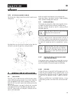
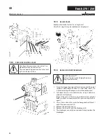
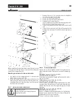
repaIrs at the unIt
10.10
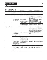
ReMedy In cASe OF FAultS
type of malfunctIon what else?
possIble cause
measures for elImInatIng the malfunctIon
Unit does not start
Motor switch can not
switched on
No voltage applied
Check voltage supply
Unit fuse has triggered
Let the motor cool down
Unit does not suck in
Air bubbles exit from
the return hose
Unit is sucking in outside
air
Check: Suction system tightened properly?
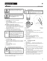
Cleaning connection at rigid suction tube
screwed tight and not leaking? Inlet valve
button leaky? -> Replace wiper and O-ring (->
refer to Section 10.1)
Air bubbles do not exit
at the return hose
Inlet valve clogged
Press the inlet valve button until the stop is
reached several times by hand
Inlet/outlet valve soiled
/ foreign bodies (e.g.
threads) drawn in / worn
Remove the valves and clean then (-> refer to
Section Pkt.10.2/10.3) / replace worn parts
Pressure control valve tur-
ned down completely
Turn the pressure control valve to the right un-
til the stop is reached
Unit does not gene-
rate pressure
Unit has sucked in
Air in the oil circuit
Bleed the oil circuit in the unit by turning the
pressure control valve completely to the left
(until overturning) and let it run approx. 2 – 3
min. Then turn the pressure control valve to
the right and set the spraying pressure (repeat
process several times, if necessary). Process is
assisted by positioning the unit vertically.
Unit reached pressu-
re, but the pressure
collapses, also at the
pressure gage, during
spraying.
Suction filter clogged
Check the suction filter. If necessary, clean/
replace
Paint cannot be worked in
this state. Due to its pro-
perties the paint clogs the
valves (inlet valve) and the
delivery rate is too low.
Dilute the paint
Unit reached pressure,
but the pressure col-
lapses during spraying.
pressure gage still
shows high pressure
Clogged filter do not let
enough paint pass
Check/clean the (high-pressure filter) gun filter
Tip clogged
Clean the tip (-> refer to Section 10.1)
Unit does not generate
the max. pressure pos-
sible. Paint neverthe-
less exits at the return
hose.
Relief valve defective
Clean or replace the relief valve (-> refer to
Section 10.5)
Содержание Finish 250
Страница 19: ...19 Finish 270 250 10 9 Schaltplan d reparaturen am ger t...
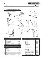
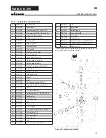
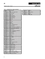
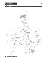
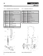
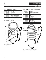
Страница 24: ...24 Finish 270 250 ersatzteile und zubeh r Ersatzteilbild Pumpenaggregat d...
Страница 48: ...48 Finish 270 250 GB Repairs at the unit 10 9 Connection diagram...
Страница 53: ...53 Finish 270 250 GB Spare parts diagram pump aggregate Spare parts and accessories...
Страница 77: ...77 Finish 270 250 10 9 Sch ma lectrique F R parations sur l appareil...
Страница 83: ...83 Finish 270 250 Illustration des pi ces de rechange du groupe de pompage pi ces de rechange et Accessoires F...
Страница 107: ...107 Finish 270 250 10 9 Elektrisch schema Reparaties aan het apparaat NL...
Страница 112: ...112 Finish 270 250 Onderdelenafbeelding pompaggregaat NL Accessoires en onderdelen...
Страница 118: ...118 Finish 270 250 NL CE Verklaring van overeenstemming...
Страница 119: ...119 Finish 270 250 NL CE Verklaring van overeenstemming...


