


SDB 412/2 SMALL DIAMETER BEVELER
BEVELING AND FACING, USING THE FLANGE
FACER MANDREL FOR CENTERING ON ELBOWS
AND BENDS.
1. Measure the pipe I. D. Select the extension leg
set required. Refer to flange facer mandrel leg
extension chart.
NOTE:
Set up the flange facing mandrel with
machine body removed.
2. Insert the legs into the mandrel head.
NOTE:
Adjustable
leg adjustment screw must be
completely tightened against leg face.
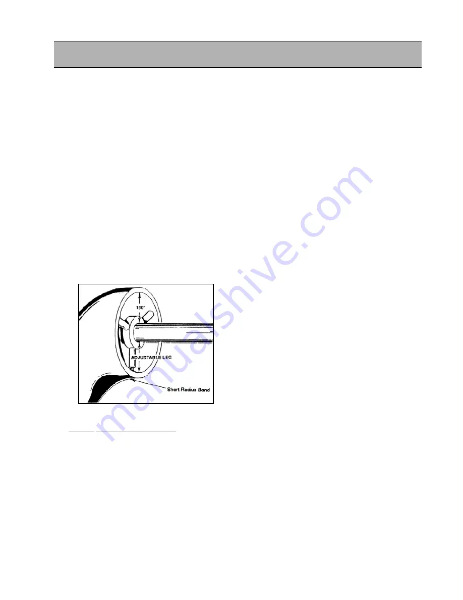
3. Place the mandrel assembly into pipe. Position
the adjustable leg at the “short radius bend”
portion of pipe,(FIG. 12) and snug the draw bar
nut.
NOTE:
Legs should be kept as close as pos-
sible to the pipe edge, yet back far enough to
perform the desired operation.
4. CHECK MANDREL CENTERING!
Measure the distance over the adjustable leg
from the pipe l.D. to the mandrel shaft. Then
measure the same distance 1800
from the
adjustable leg. When the mandrel is centered,
these two measurements will be approximately
equal.
NOTE:
If additional centering is required and man-
drel removal is necessary, utilize the alignment
fixture to insure returning the legs to the original
set up location. Place the alignment fixture on the
mandrel shaft, push it forward to meet the pipe
face, and snug the fixture in place. Remove the
mandrel; make the leg adjustment needed. Re-
insert the mandrel and alignment fixture. Make sure
(Fig. 12)
the adjustable leg is located at the ”short radius bend“.
Push the assembly tight against the pipe face and
tighten the mandrel. The legs should be at the origi
nal set up location. If the pipe end is square the align
ment fixture will square the mandrel shaft to the pipe.
5. If additional centering is required, loosen the
mandrel and adjustable leg.
NOTE:
One complete revolution of the adjustment
screw is equal to 0.050 thousandths (1.19 mm) of
travel on the small legs and .056 thousandths on
the large leg sets.
EXAMPLE:
If the distance over the adjustable leg,
between the mandrel shaft and pipe I. D. is one inch
(1”) and the distance 180° from the adjustable leg ,
between the mandrel shaft and the pipe I. D.,
is 1-1/8” divide the difference in half.
1/8” (.125) + 2 =.0625 (1/16”)
Rotate the adjustable leg out approximately one
and 1/8 turns.
6. Re-insert the mandrel after making the centering
adjustments, Measure for centering again. Repeat
if necessary.
7. If the elbow or bend has a square end, utilize the
alignment fixture to square the mandrel shaft. Place
the fixture on the mandrel shaft and push it forward
to meet the pipe face; snug the fixture in place.
Loosen the mandrel assembly slightly push the
fixture forward until it rests firmly against the pipe
face, and retighten the mandrel.
8. If the elbow or bend has been cut and is not square,
a reference point for squaring should be established.
9. Once established, install the alignment fixture on
the mandrel, pushing it firmly against the pipe face.
Position the three legs so that one of the three
jacking set screws in each leg is positioned over the
pipe face. Screw in the jacking set screws until the
back side of the fixture plate is square to the ref-
erence point.
17
Содержание FF 424
Страница 2: ......
Страница 6: ...SDB 412 and FF 424 4 Part No 66 MAN 01 Rev A E H Wachs...
Страница 12: ...SDB 412 and FF 424 10 Part No 66 MAN 01 Rev A E H Wachs...
Страница 24: ...22...
Страница 40: ...SDB 412 and FF 424 38 Part No 66 MAN 01 Rev A E H Wachs SDB 412 Air Drive 66 000 01 NOTE...
Страница 41: ...Operating Envelopes E H Wachs Part No 66 MAN 01 Rev A 39 SDB 412 Hydraulic Drive 66 000 03 NOTE...
Страница 48: ...SDB 412 and FF 424 46 Part No 66 MAN 01 Rev A E H Wachs...
Страница 66: ...SDB 412 and FF 424 66 Part No 66 MAN 01 Rev A E H Wachs...
Страница 69: ......
Страница 70: ...600 Knightsbridge Parkway Lincolnshire IL 60069 847 537 8800 www ehwachs com...