VorTek SonoPro S34 Series Скачать руководство пользователя страница 32

Series S34 Instruction Manual 

Chapter 3 Operation


3-3 

M-000-00030


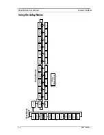
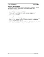
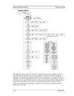
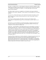
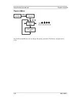
Using the Setup Menus 


O

ut

pu

t

M

en

u

D

is

pl

ay

M

en

u

M

en

u

M

en

u

M

en

u

M

en

u

M

en

u

M

en

u

Pa

ss

w

or

d

M

en

u

Pa

ss

w

or

d

To

 p

ag

3-

5

E

N

T

E

R

To

 p

ag

3-

7

To

 p

ag

3-

8

To

 p

ag

3-

11

To

 p

ag

3-

12

To

 p

ag

3-

13

To

 p

ag

3-

14

To

 p

ag

3-

15

To

 p

ag

3-

17

M

as

Fl

ow

R

at

e

Vo

lu

m

e

Fl

ow

 R

at

e

Te

m

pe

ra

tu

re

D

en

si

ty

To

ta

l

Al

ar

m

 1


St

at

us

Fl

ui

d

E

N

T

E

R

D

at

Ti

m

Al

ar

m

 2

St

at

us

R

u

n

 M

o

d

e

S

c

re

e

n

s

S

e

tu

p

 M

e

n

u

s


M

en

u

To

 p

ag

3-

9

En

er

gy

M

en

u

To

 p

ag

3-

10

En

er

gy

*

*

*

*

E

n

e

rg

y


M

e

te

rs

 O

n

ly

M

en

u

To

 p

ag

3-

16

C

al

ib

ra

tio

n

D

ia

gn

os

tic

s

Ti

m

D

at

U

ni

ts

To

ta

liz

er

 #

2

To

ta

liz

er

 #

Al

ar

m

s

Fl

ui

d

To

ta

l 2

Ba

tte

ry

 x

%

*


Содержание SonoPro S34 Series

Страница 1: ...ents M 000 00030 0 1 SonoPro Portable Ultrasonic Flow Meter Series S34 Instruction Manual Document Number M 000 00030 Rev A 8475 W I 25 Frontage Rd Suite 300 Longmont CO 80504 303 682 9999 888 386 783...

Страница 2: ...puter language in any form or by any means electronic mechanical manual or otherwise or disclosed to third parties without the express written permission of VorTek Instruments The information containe...

Страница 3: ...2 Series S34 Clamp On Flow Meter Installation 2 3 Transducer Mounting Methods 2 3 Large Rail Fixture System 2 5 Adjacent Side Transducer Installation 2 5 Opposite Side Transducer Installation 2 7 Sma...

Страница 4: ...ostics Menus 6 1 Level One Hidden Diagnostics Values 6 3 Level Two Hidden Diagnostics Values 6 4 Analog Output Calibration 6 7 Troubleshooting the Flow Meter 6 8 First Check Items 6 8 Record Values 6...

Страница 5: ...t Diagram 2 13 2 14b 3 and 4 Wire RTD Input Wiring 2 14 2 15 IDC Connector Open Position 2 14 2 16a IDC Connector Closed Position 2 15 2 16b IDC Connector Closed Position with Wires 2 15 2 17 Load Res...

Страница 6: ...in accordance with published CE directives All wiring proce dures must be performed with the power off Always remove main power before disassembling any part of the flow meter Caution In order to achi...

Страница 7: ...isplay which provides instantaneous flow rate total and process parameters in engineering units A pulse output signal for remote totali zation and frequency output are also available SonoPro digital e...

Страница 8: ...tributor Remove the packing slip and check that all ordered components are present Make sure any spare parts or accessories are not discarded with the packing material Do not return any equipment to t...

Страница 9: ...e measurement two ultrasonic transducers are mounted onto the outside of the pipe With one being downstream at a designated distance from the other The electronics send two pulses through the pipe and...

Страница 10: ...y and external RTD VET velocity and external temperature transmitter pending VorTek Instruments LLC is consulted with prior VERER velocity two external RTDs Line Size Materials The SonoPro meter can b...

Страница 11: ...r 1 Introduction 1 5 M 000 00030 The electronics include nonvolatile memory that stores all configuration infor mation The nonvolatile memory allows the flow meter to function immediately upon power u...

Страница 12: ...e will not exceed the flow meter rating 2 The location meets the required minimum number of pipe diam eters upstream and downstream of the sensor head as illustrated in Table 2 1 3 Safe and convenient...

Страница 13: ...ed number of straight run pipe diameters upstream and down stream of the sensors Note For liquid applications in vertical pipes avoid installing with flow in the downward direction because the pipe ma...

Страница 14: ...a minimum Transducer Mounting Methods There are three typical mounting methods available These include the Z method which is a single traverse across the pipe the V method which is two traverses acro...

Страница 15: ...tallation Method 2 MHz transducers shown Figure 2 3 Z One Traverse Once the installation method is chosen you will then need to refer to Chapter 3 for programming the unit for the actual application T...

Страница 16: ...loose fit 4 Loosen the two set screws on the rightmost transducer mounting clamp and using the scale etched on the front most rail slide the clamp so that the back edge of the side bracket is at the l...

Страница 17: ...et screws Tighten the screw with plastic knob on the top of the mounting clamp so the end of the screw fits into the divot on the top of the transducer 7 Tighten the chain using the thumb nut on the f...

Страница 18: ...tight on the pipe 7 Tighten the screw with plastic knob on the top of the transducer mounting clamp so the transducer fits tight on the pipe Do not over tighten 8 Position the second transducer mount...

Страница 19: ...Series S34 Instruction Manual Chapter 2 Installation M 000 00030 2 8 Figure 2 6 Opposite Side Transducer Installation Front View Figure 2 7 Opposite Side Transducer Installation Side View...

Страница 20: ...Series S34 Instruction Manual Chapter 2 Installation M 000 00030 2 9 Figure 2 8 Opposite Side Transducer Installation Angled View Small Rail Fixture System Figure 2 9 Small Rail Fixture System...

Страница 21: ...cer mounting clamp and using the scale attached to the front rail slide the clamp so that the middle of the bracket is close to the location determined by the flow meter See Figure 2 11 for reference...

Страница 22: ...sducer is fitted move the clamp so that the scribe line on the transducer is placed at the flow meter s determined location Refer to the green arrow in Figure 2 11 for this locating point Tighten the...

Страница 23: ...enience Note there is a key on the male connector found on the transducer and a keyway on the female connector found on the top of the handheld unit The key on the male end of the connector must be pl...

Страница 24: ...details the input wiring for 3 wire and 4 wire RTDs The SonoConnect breakout box utilizes special IDC connectors that do not require the insulation of the wire to be stripped prior making a connection...

Страница 25: ...To connect a 3 wire RTD split the single wire into two separate wires see the circle in the bottom diagram of Figure 2 14b and connect these to the EXCITE and SENSE H terminals in the SonoConnect brea...

Страница 26: ...Series S34 Instruction Manual Chapter 2 Installation M 000 00030 2 15 Figure 2 16a IDC Connector Closed Position Figure 2 16b IDC Connector Closed Position with Wires...

Страница 27: ...L 23 RTD1 SENSE H 10 RTD1 EXCITE 22 N A ISOLATED ANALOG INPUT A_IN 9 ISOLATED ANALOG INPUT A_IN 21 Totalizer RELAY 8 RELAY 20 ALARM 2 ALARM2 7 ALARM2 19 RTD 2 RTD2 RETURN 6 RTD2 SENSE L 18 RTD2 SENSE...

Страница 28: ...t loop output is dependent upon the supply voltage and is given in Figure 2 18 The 4 20 mA loop is optically isolated from the flow meter electronics Rload is the total resistance in the loop includin...

Страница 29: ...he meter electronics and power supply Figure 2 19 Isolated Pulse Output Using External Power Supply Frequency Output Connections The frequency output is used for a remote counter of the flow rate It c...

Страница 30: ...for flow monitoring and programming The tactile mem brane keypad makes it easy to read the measured parameters or pro gram the meter Battery LEDs Each keypad comes standard with two LEDs The left LED...

Страница 31: ...ar 2 The Run Mode displays flow information as determined by system settings Some screens depicted on the next page may not be displayed based on these settings Press the ar row keys to view the Run M...

Страница 32: ...3 8 To page 3 11 To page 3 12 To page 3 13 To page 3 14 To page 3 15 To page 3 17 Mass Flow Rate Volume Flow Rate Temperature Density Total Alarm 1 Status Fluid ENTER Date Time Alarm 2 Status Run Mod...

Страница 33: ...to customize the multi parameter features of your SonoPro Flow Meter The entire lower display line is available for entering parameters Some items depicted in the graphic on the preceding page may not...

Страница 34: ...Series S34 Instruction Manual Chapter 3 Operation 3 5 M 000 00030 Output Menu...

Страница 35: ...inator Press the key until hr appears in the denominator Press ENTER to select 4 Press key until Units Menu appears Second set the analog output 1 Use keys to move to the Output Menu 2 Press the key u...

Страница 36: ...Yes Display smoothing Yes or No E Energy Energy EMS Meters Only Use keys to access menus Use the Display Menu to set the cycle time for automatic screen sequencing used in the Run Mode change the prec...

Страница 37: ...arm activates Note all outputs are disabled while using the Setup Menus First set the desired units of measurement 1 Use keys to move to the Units Menu see page 3 13 2 Press key until Mass Flow Unit a...

Страница 38: ...ond Example for Setting the Totalizer The following shows how to set the totalizer to track mass flow in kg sec Note all outputs are disabled while using the Setup Menus First set the desired units of...

Страница 39: ...030 Totalizer 2 Menu Password ENTER Use keys to access menus Totalizer Menu ENTER Run Mode Totaling Inactive Mass Volume Energy Reset Total YES or NO Use the Totalizer 2 to Monitor Flow or Energy Note...

Страница 40: ...w Line Sent Flow Line Change in Energy Water Sent Flow Line None Outgoing Energy As above you must properly configure the meter in the Energy Menu 1 Loc in Sent Flow Select Yes or No based on where th...

Страница 41: ...nu Password ENTER Fluid Menu Flowing Fluid Liquids ENTER Run Mode Use keys to access menus Liquid Water Ethylene Glycol Volume 68 Deg F xx Density xxxx AL xxxx BL xxxx Other Liquid Sound Speed ft s xx...

Страница 42: ...lG ImpG bbl lit MilL m3 ft3 Temperature Unit Deg F Deg C Kelvin Rankine Density Unit lbm ft3 kg m3 gm cc lbm gal gm mlit kg lit gm lit lbm in3 MilG Million gallons Imperial gallon 1 20095 US gallons b...

Страница 43: ...format is used to set the time For example 1 00 PM is entered as 13 00 00 in the Set Time menu Example for Setting the Time How to set the time to 12 00 00 You can check the time in the Run Mode by p...

Страница 44: ...of sound The closer the value is to 1 the stronger the correlation Signal Quality is a measure of the amplitude of the ultrasonic signal from 0 to 100 that is normalized for gain fluid and pipe mater...

Страница 45: ...formation will be preconfigured in the meter otherwise it is needed at the time of installation to properly program the unit Note once the information is programmed the meter will calculate the proper...

Страница 46: ...sducers are being installed for measurement Fluid Temp 1 is the temperature of the liquid inside the pipe The temperature can be entered manually by selecting Don t Use RTD It can also be measured wit...

Страница 47: ...Chapter 3 Operation 3 18 M 000 00030 Password Menu Password ENTER Use keys to access menus Password Menu Set Password 1234 ENTER Run Mode Use the Password Menu to set or change the system password The...

Страница 48: ...see Chapter 5 SonoConfig Instrument Interface Software The SonoPro App Programming the Unit to Log Data 1 Press ENTER on the keypad of your portable ultrasonic handheld unit The text in Figure 4 1 wi...

Страница 49: ...resented in this image may not match your unit This is normal Figure 4 5 Second Level of Hidden Diagnostics Menu 6 Using the up or down arrow scroll to find the Logging submenu as shown in Figure 4 6...

Страница 50: ...the format of YYYYMMDD log at the end of each day You have the option to select four variables from the following list See Figure 4 8 for a screen capture of how these menus will look on the SonoPro h...

Страница 51: ...00 00030 4 4 Figure 4 8 Logging Variables 9 Once the four variables are defined press the EXIT button until you are prompted to Save Changes Select YES or NO press ENTER and you will be returned to th...

Страница 52: ...logging tools Communicate with SonoPro Portable through Bluetooth wireless or direct wire communication SonoConfig is available for download through VorTek Instruments LLC website vortekinst com An im...

Страница 53: ...Series S34 Instruction Manual Chapter 5 SonoConfig Instrument Interface Software 5 2 M 000 00030 Figure 5 2 Screenshot of Waveforms Tab on SonoConfig...

Страница 54: ...Press EXIT to move from the second level back to the first press EXIT while in the first level to return to the setup menus Caution password 16363 will allow full access to the configuration and shou...

Страница 55: ...Series S34 Instruction Manual Chapter 6 Troubleshooting and Repair M 000 00030 6 2 Hidden Diagnostics Menus...

Страница 56: ...ected Yes or no Battery I and V Current and voltage of the internal battery Positive current is battery charging Negative current is battery discharging Battery Charge Total and remaining capacity of...

Страница 57: ...he Gain to calculate the Signal Strength Down Peak The A D counts of the downstream sound wave representing the amplitude of the signal Each stage has a maximum value of 511 The A D counts will increa...

Страница 58: ...h 10 Velocity 1 through 10 Absolute Abs Roughness in Factory use only Force Recal Factory use only Erase FRAM Factory use only Min Delta H Energy EMS meters only Sets the deadband for totalization to...

Страница 59: ...e value calculated by the application i e value calculated from transducer pipe size fluid setup temp etc This is used when the received waveform is not in the sampling window especially the wave fron...

Страница 60: ...the second level of the hidden Diagnostics menu and then actuate the ENTER key This action will cause the meter to output its 4 mA or 20 mA condition If the DVM indicates a current greater than 0 006...

Страница 61: ...ation Correct Describe Installation Geometry i e upstream diameters valve position downstream diameters etc Record Values Record the following values from the Run Menu with the meter installed in orde...

Страница 62: ...With No Flow if possible Avg Delta T Up Peak Down Peak Zeros in Signal Wave Freq Cutoff V SR Coefficient Num Cycles Waveform Manual Flight Wave Simulation Record the following values from the Calibra...

Страница 63: ...tom No Output or Empty Pipe Detected 1 Verify that there is fluid in the pipe and that there is a full pipe condition The flow meter will not read depending on the mounting position of the transducer...

Страница 64: ...econd Level of the Hidden Diagnostics menu a This parameter should be set to a value of 1 0 by default If this value is not set to 1 0 and you have not been instructed to change it please change it ba...

Страница 65: ...menu a Num Cycles This parameter is used to define the number of cycles or pulses being sent by the driving circuit to try and determine the flow rate of the fluid in the pipe You can select between...

Страница 66: ...Manual Chapter 6 Troubleshooting and Repair M 000 00030 6 13 If your problem persists run through the First Check Items in the beginning of this chapter fill in the Record Values Section and contact t...

Страница 67: ...rrect shipping address submit a request through VorTek Instruments LLC website vortekinst com or contact Customer Service at 888 386 7835 or 303 682 9999 in the USA When contacting Customer Service be...

Страница 68: ...election Measurement Parameters Volume Flow Mass Flow Density Temperature Energy Units Temperature Range Standard Temperature 4 F to 248 F 20 C to 120 C Electronics Specifications Power Supply 100 to...

Страница 69: ...Series S34 Instruction Manual Appendix A Specifications A 2 M 000 00030...

Страница 70: ...0030 B 1 Appendix B Flow Meter Calculations Volume Flow Rate Mass Flow Rate Where A Cross sectional area of the pipe ft 2 C speed of sound L sound path length QM Mass flow rate lbm sec Qv Volume flow...

Страница 71: ...the International Association for the Properties of Water and Steam IAPWS Industrial Formulation 1997 for the Thermodynam ic Properties of Water and Steam Viscosity The liquid viscosity is found using...

Страница 72: ...303 10236 18525 Stainless 304 10305 12 19094 49 Stainless 304L 10073 19000 Stainless 316 10735 18750 Copper 7415 15291 67 Annealed Copper 7628 0 0 Rolled Copper 7448 0 0 Naval Brass 6923 14533 33 Iro...

Страница 73: ...Series S34 Instruction Manual Appendix C Sound Speed and Pipe Data C 2 M 000 00030 Pipe Chart...

Страница 74: ...Series S34 Instruction Manual Appendix C Sound Speed and Pipe Data C 3 M 000 00030...

Страница 75: ...Series S34 Instruction Manual Appendix C Sound Speed and Pipe Data C 4 M 000 00030...

Страница 76: ...Series S34 Instruction Manual Appendix C Sound Speed and Pipe Data C 5 M 000 00030...

Страница 77: ...Series S34 Instruction Manual Appendix C Sound Speed and Pipe Data C 6 M 000 00030...

Страница 78: ...Series S34 Instruction Manual Appendix C Sound Speed and Pipe Data C 7 M 000 00030...

Страница 79: ...Series S34 Instruction Manual Appendix C Sound Speed and Pipe Data C 8 M 000 00030...

Страница 80: ...he current configuration d Press the up down arrow to return to the Fluid menu 4 Using the right arrow navigate to the Units menu a Using the up down arrow define the required units 5 Using the right...

Страница 81: ...Save Changes 8 Install the Rail Fixture System on to the pipe a Adjacent side transducer installation method i V and W methods of measurement 1 Refer to page 2 5 in the manual for detailed installati...

Страница 82: ...nd or pressure CSA Canadian Standards Association D Diameter of a flow channel E F G H Flow Channel A pipe duct stack or channel containing flowing fluid Flow Profile A map of the fluid velocity vecto...

Страница 83: ...of the fluid channel divided by the fluid viscosity i e Re VD The Reynolds number is an important number for vortex flow meters because it is used to determine the minimum measurable flow rate It is t...

Отзывы: