


Series S34 Instruction Manual
Chapter 2 Installation
M-000-00030
2-13
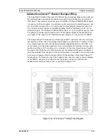
Optional SonoConnect
™
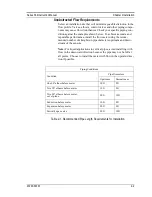
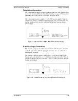
Breakout Box Input Wiring
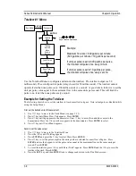
The SonoPro® Portable Ultrasonic Flow Meter has an optional breakout box that can
be purchased that will unlock the features typically found on that of a fixed mount
flow meter. This includes inputs for up to two RTDs (VER and VERER-EM models),
two analog (4-20mA) outputs, two alarms, a pulse output, and a scaled frequency out-
put. In addition, support for a 4-20 mA input for a temperature transmitter and up to
two contact closures inputs are available pending VorTek Instruments, LLC is con-
sulted with prior. For VER and VERER-EM models, a 3 or 4-wire RTD may be used.
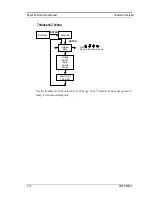
For details on the description and location of the inputs/outputs of the breakout box,
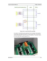
see Figure 2-14a. Figure 2-14b details the input wiring for 3-wire and 4-wire RTDs.
The SonoConnect
™
breakout box utilizes special IDC connectors that do not require
the insulation of the wire to be stripped prior making a connection. To make a connec-
tion, simply insert the wire into the open terminal (angled position) on the IDC con-
nector and set it to the closed position. Note, to determine if a terminal is in the open
position see Figure 2-15, and to see if a terminal is in the closed position see Figure 2-
16a and 2-16b. With the wire fully inserted, use the included flat head screwdriver to
push the terminal from the open, to the closed position. A secondary set of connectors
with screw terminals will also be provided
with the purchase of the SonoConnect™
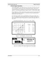
breakout box. For instances where the breakout box cannot be used, a pinout diagram
of the DB25 connector, the connector used to make a connection between the
handheld unit and the breakout box, is provided in Figure 2-17.
Figure 2-14a. SonoConnect
™
Wiring Pinout Diagram
Содержание SonoPro S34 Series
Страница 34: ...Series S34 Instruction Manual Chapter 3 Operation 3 5 M 000 00030 Output Menu...
Страница 55: ...Series S34 Instruction Manual Chapter 6 Troubleshooting and Repair M 000 00030 6 2 Hidden Diagnostics Menus...
Страница 69: ...Series S34 Instruction Manual Appendix A Specifications A 2 M 000 00030...
Страница 73: ...Series S34 Instruction Manual Appendix C Sound Speed and Pipe Data C 2 M 000 00030 Pipe Chart...
Страница 74: ...Series S34 Instruction Manual Appendix C Sound Speed and Pipe Data C 3 M 000 00030...
Страница 75: ...Series S34 Instruction Manual Appendix C Sound Speed and Pipe Data C 4 M 000 00030...
Страница 76: ...Series S34 Instruction Manual Appendix C Sound Speed and Pipe Data C 5 M 000 00030...
Страница 77: ...Series S34 Instruction Manual Appendix C Sound Speed and Pipe Data C 6 M 000 00030...
Страница 78: ...Series S34 Instruction Manual Appendix C Sound Speed and Pipe Data C 7 M 000 00030...
Страница 79: ...Series S34 Instruction Manual Appendix C Sound Speed and Pipe Data C 8 M 000 00030...


