background image


47 


Representation in display LCD 

Alarms 

Alarm NO. 

Rectifier Overload.   

RECTIFIER 

Inverter Overload.   

INVERTER 

Mains Failure. Battery Low Level.   

Inverter Voltage Out of Margins.   

DC Voltage Detected at the Output.   

Maintenance Bypass. Inverter Not 
Available.   

Battery Discharging.   

UPS 

High Temperature. Reduce Output 
Load.   

Battery Switch Open. Switch it ON.   

Bypass Failure. Not Synchronised 
Inverter.   

10 

Unit on Bypass. Initialise UPS.   

11 

Some Unit(s) Blocked due to 
Maintenance Bypass.   

12 

CAN BUS 1 Communication Failure.   

13 

CAN BUS 2 Communication Failure.   

14 

End of Battery Life.   

15 

Battery Temperature too High.   

16 

Battery Test Not Succeeded.   

17 

Battery Disconnection. Shutdown & 
Restart.   

18 

Mains Phase Rotation. UPS Start 
Disabled.   

19 

Bypass Phase Rotation. UPS Start 
Disabled.   

20 

EEPROM Failure. 

77 

Input Voltage Wrong. Rectifier Stop.   

RECTIFIER 

STOPS 

21 

Rectifier Desaturation. Rectifier 
Stop.   

22 

DSP Internal Error. Rectifier Stop.   

23 

Input Phase Rotation. Rectifier Stop.   

24 

DC BUS Voltage Wrong. Rectifier 
Stop.   

68 

Parallel System Rectifier Stop.   

69 

Cont. Test Fail Rectifier Stop.   

75 

Inverter Desaturation. Inverter Stop.   

INVERTER 

STOPS 


25 

Inverter Overload. Inverter Stop.   

26 

Inverter Stopped due to Shutdown.   

27 

Maintenance Bypass. Inverter Stop.   

28 

Parallel System Disconnection. 
Inverter Stop.   

29 

High Overload. Inverter Stop.   

30 

Over-temperature. Inverter Stop.   

31 

Rectifier Overload. Inverter Stop.   

32 

DSP Internal Error. Inverter Stop.   

33 

Output Short-circuit. Inverter Stop.   

34 

Bypass Phase Rotation. Inverter 
Stop. 

35 

Inverter Failure/Overload. Inverter 
Stop.   

65 

Voltage Ramp Error. Inverter Stop.  

67 

Parallel System Inverter Stop.   

70 

Low Battery. UPS Stop.   

36 

DSP Internal Error. UPS Stop.   

UPS 

STOPS 

37 

Pfc., Inv. Stop UPS Stop.   

71 

Parallel System UPS Stop.   

72 

Emergency Power Off. No Output 
Voltage.   

BYP 

STOPS 


38 

Output Short-circuit. No Output 
Voltage.   

39 

DSP Internal Error. UPS Block All.   

40 

DC BUS Voltage Wrong. Rectifier 
Block.   

RECTIFIER 

BLOCKS 

41 

Rectifier Blocked. BLK. UPS -> BLK 
Rectifier.   

42 

Rectifier Desaturations. Rectifier 
Block.   

43 

Voltage Ramp Error. Rectifier Block.   

44 

DSP Execution Error. Rectifier Block.   

45 

DSP Internal Error. Rectifier Block.   

46 

Contactor Test Failure. Rectifier 
Block.   

47 

Voltage Ramp Error. Inverter Block.   

INVERTER 

BLOCKS 

48 

Output DC Voltage. Inverter Block.   

49 

Inverter Blocked. BLK. UPS -> BLK 
Inverter.   

50 

Inverter Desaturations. Inverter 
Block.   

51 

DSP Execution Error. Inverter Block.   

52 

 DSP Internal Error. Inverter Block.   

53 

Inverter Failure. Inverter Block.   

66 

UPS Blocked. BLK. Rectifier -> 
BLK. UPS.   

UPS 

BLOCKS 

54 

Internal Initialisation Error. UPS 
Block (DSP).   

55 

Internal Execution Error. UPS Block 
(DSP).   

56 

UPS Blocked. BLK. Inverter -> BLK. 
UPS.   

57 

Internal Communication. UPS Block 
(DSP).   

58 

Parallel System Discharging. UPS 
Block.   

59 

UPS Over-temperature. UPS Block.   

60 

Rectifier Overload. UPS Block.   

61 

Inverter Desaturations. UPS Block.   

62 

DSP Internal Error. UPS Block.   

63 

PFC & Inverter Blockage. UPS Block.   

64 

Parall0. Coms Error UPS Block.   

76 

Error Coms. Paral. Master Fixed.   

PARALLEL 

73 

Alarm Paral. Sist. Redundancy Lost.   

74 

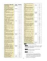
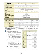
Table .5  Alarm list displayed in the LCD panel. 
 

˙

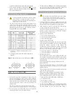
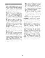
Alarm 16: The temperature of battery cabinet (in case of separate 
battery cabinet) or battery place (in case of battery are located 
inside the UPS) is higher than 40ºC. 


˙

Alarm 17: If battery test (automatic or manual) is finished 
unsuccessfully, this alarm will appear. 


˙

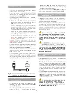
Alarm 18: Two possible reasons: 


During the unit start up, a message appears indicating 
that the battery switch can be switched ON. After some 
period of time without switching ON, this alarm appears. 

  When the unit is running under normal conditions, and 

the battery switch is switched OFF. 

Содержание Taurus UPS-10

Страница 1: ...7 Touch LCD Online UPS 208V 7 5K 60KVA 400V 10K 200KVA Uninterruptible Power Supply System User Manual...

Страница 2: ...X4 5 2 2 Connection of separate static bypass line terminals X14 a X17 UPS B version only 5 2 3 Connection to the output terminals X6 to X9 5 2 4 Connection to the battery terminals of the equipment...

Страница 3: ...hand during the installation and commissioning procedures In the next pages the equipment or unit and S T S terms are referred to the Uninterruptible Power Supply UPS and Service and Technical Support...

Страница 4: ...urrent a c Direct current d c 2 1 2 For more information and or help For more information and or help of your specific unit request it to our Service and Technical Support S T S 2 2 SAFETY INSTRUCTION...

Страница 5: ...any installation task Do not store install or expose the equipment in corrosive wets warm dusty environments or with conductive parts and never outdoors The best location for installation should be c...

Страница 6: ...ration Once the respective actions are completed recover the equipment to it was with the protection cover put back and front door closed To shut down the equipment completely follow the instructions...

Страница 7: ...ied personnel who will be responsible for applying the safety and EMC regulations and standards controlling the particular installations and the place where the product is destined 2 2 3 Safety warnin...

Страница 8: ...particular due to this last period and safety reasons the energy generator should be handled with care especially to prevent batteries from unnecessarily discharging during these periods of time When...

Страница 9: ...ers EN IEC 60950 1 IT equipment Safety Part 1 General requirements EN IEC 62040 2 Uninterruptible power supply UPS Part 2 EMC requirements The manufacturer s responsibility excluded the event of any m...

Страница 10: ...of the same family because the necessary electronic kit is included Connection in parallel can be done at any time when the upgrading requirements are needed to increase the supplied power of the equi...

Страница 11: ...from 7 5 to 30 kVA LV 10to 60 kVA HV with or without separate static bypass line B Fig 2 UPSfrontview from 40 to60kVA LV 80 to120kVA HV without separate static bypass and 40 kVA LV 80 kVA HV with sep...

Страница 12: ...CD Touch Screen View 1 Equipment with extended back up time only Fig 4 UPS Front view with door opened 7 5KVA to 20KVA LV 10KVA to 40KVA HV models Fig 5 UPS Front view with door opened 30KVA LV 60KVA...

Страница 13: ...iew with door opened 7 5KVA to 10KVA LV 10KVA to 20KVA HV models with separate static bypass line UPS B models Fig 7 UPS Front view with door opened 15KVA LV 30KVA HV models with separate static bypas...

Страница 14: ...12 Fig 8 UPS Front view with door opened models 20KVA LV 40KVA HV with separate static bypass line UPS B models Fig 9 UPS front view with door opened models 40kVA LV 80KVA HV...

Страница 15: ...13 Fig 10 UPS front view with door opened models 50 and 60 kVA LV 100 and 120 kVA HV without separatestatic bypass line...

Страница 16: ...14 Fig 11 UPS front view with door opened models 80 and 100 kVA LV 160 and 200 kVA HV without separatestatic bypass line...

Страница 17: ...15 Q8 X47 X49 X48 BF X5 PR X10 Fig 12 Battery cabinet front view No 1 with door closed Fig 13 Battery cabinet front view No 1 with door opened...

Страница 18: ...16 Q8 X47 X49 X48 X5 PR X10 Fig 14 Battery cabinet front view No 2 with door closed Fig 15 Battery cabinet front view No 2 with door opened...

Страница 19: ...17 Fig 16 Battery cabinet front view No 3 with door closed Fig 17 Battery cabinet front view No 3 with door opened...

Страница 20: ...static bypass phase R B version only X15 Terminal of static bypass phase S B version only X16 Terminal of static bypass phase T B version only X17 Terminal of static bypass neutral N B version only 1...

Страница 21: ...ng BL of switch Q5 By means of the connectors X36 and X36 the communication loop or ring is closed between two or more equipment connected in parallel by means of the bundle BC These connectors are no...

Страница 22: ...s it is used to filter the DC needed for the correct operation of PFC converter and inverter 4 3 3 Batteries This UPS series has a battery set that stores energy during the normal operating mode prese...

Страница 23: ...hem The bypass stage is based on six double thyristors in semipack format working as AC switches three of them are for shifting the input over the output and the other three are for shifting the inver...

Страница 24: ...consigning a battery discharging current even with existing mains This quality performance will make it possible to do a battery test both in full load and in no load conditions Output three phase rec...

Страница 25: ...d in the previous section 4 4 1 Normal operating 4 4 3 Operating with non active inverter The inverter is non active due to alarm conditions like overloads over temperatures etc In this case the recti...

Страница 26: ...W N Inp Out COM connections Inp Out Fig 22 Single line diagram connection of parallel system up to 4 units of UPS models COM connections Inp Out R S T N R S T N COM connections U V W N Inp Out COM con...

Страница 27: ...ures a quality of AC power supply for the most critical loads The quantity of redundant equipment to be connected has to be studied according to the requirements of the application No matter Parallel...

Страница 28: ...attached to the impact indicator located on the packaging Unpacking Check the content before deserting the packaging Unpack the package according to the Unpacking procedure in the supplied document in...

Страница 29: ...nce of the floor kg m2 25 cm 25 cm 150 cm 25 cm 25 cm 5 1 4 Location immobilization and considerations 5 1 4 1 Location for single equipment As i e Fig 24 itshows two typical cases depending on the mo...

Страница 30: ...ion referred to the installation of a single equipment or parallel system Switchgear or external manual bypass panel boards It is advisable to have an external manual bypass panel board equipped with...

Страница 31: ...r power rate are supplied in a separate cabinet Therefore battery protection is arranged as follows In the UPS stated in this document as Q3 Battery fuse holder switch with 3 fuses in models up to 20...

Страница 32: ...ipment Connection to three phase mains Connect the power supply cables R S T N to the input terminals X1 X2 X3 and X4 respecting the phase rotation and neutral indicated on the label of the equipment...

Страница 33: ...loads to U V W N output terminals X6 X7 X8 and X9 respecting the phase rotation and neutral indicated on the label of the equipment and in this manual If the phase rotation is not respected the equip...

Страница 34: ...ng one side to terminals X11 X23 and X12 of UPS and the other one to terminals X47 X49 and X48 of battery module always respecting the stated polarity on the labelling of each element and this manual...

Страница 35: ...a communication cable of just 3 wires Physical structure of the RS 232 Pin 2 RXD Serial data reception Pin 3 TXD Serial data transmission Pin 5 GND Ground signal Physical structure of the RS 485 Unli...

Страница 36: ...that allows compensating the floating voltage according to the ambient temperature Any wire connected to the terminals X34 X45 and X51 will be entered into the equipment through the cable bushing PR...

Страница 37: ...cation BUS To do it connect them in a sequential way two lines of the communication BUS between a unit and its adjacent Together with each UPS of a parallel system it is supplied a 15 wires bundle wit...

Страница 38: ...ts to be a guide to clarify the possible doubts on how the communication loop has to be connected To see the physical layout of the COM connectors for each power rate refer to the illustrations of fig...

Страница 39: ...n mean while the input voltage is available In those installations without the external manual bypass panel board omit the actions and steps that involve the maneuvering of their switches Fig 33 Proce...

Страница 40: ...UPS in the system Turn the input switch Q1a to On position for each UPS in the system Each display of the Control Panel will be turned on automatically Do not close any other switches at this time Re...

Страница 41: ...trol panel Turn the output switch Q2 of the UPS On 6 5 COMPLETE SHUTDOWN OF THE UPS Shutdown the loads If the system has outgoing distribution protections switch them Off Shutdown the inverter Please...

Страница 42: ...maintenance bypass to normal operation In model with external battery cabinet set fuse holder switch from battery cabinet Q8 to On position In standard units set the input switch Q1a to On position I...

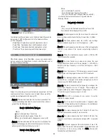
Страница 43: ...home from any screen of any submenu we can go back to main screen Screen 0 0 Fig 35 Screen 0 0 Main Screen 7 2 2 CONTROL Level screen menu 1 0 Screens 1 1 and Screen 1 2 It s to start and stop the un...

Страница 44: ...about the battery test is given Possible messages EXECUTING The battery test is running SUCCESSFUL The battery test has been successful NOT SUCCESSFUL The battery test has not been successful Screen...

Страница 45: ...urrent for three phase equipment per phase for single phase equipment accuracy 0 1A Charging Current Positive and negative accuracy 0 1A Discharging Current Positive and negative accuracy 0 1A Screen...

Страница 46: ...he options are the following SEC MODBUS Screen 3 3 Automatic battery test setting The options for the Type to be programmed are the following DISABLED The automatic battery test is disabled WEEKLY The...

Страница 47: ...this level an authorized password will be required to modify some advanced parameters If you need to modify advanced setting please check with your dealer to get password Screen 3 5 Rated Value To mod...

Страница 48: ...m appears when the input the unit is under main failure condition and the level of battery is lower than 11 5V bat Alarm 4 This alarm appears when the inverter output voltage phase to neutral in any p...

Страница 49: ...op UPS Stop 71 Parallel System UPS Stop 72 Emergency Power Off No Output Voltage BYP STOPS 38 Output Short circuit No Output Voltage 39 DSP Internal Error UPS Block All 40 DC BUS Voltage Wrong Rectifi...

Страница 50: ...l be blocked after 30 and a blocking alarm 61 will appear Alarm 33 This alarm appears when there is a DSP Internal Error in the inverter module shutting down the inverter immediately There will be 4 m...

Страница 51: ...ed Alarm 64 If there is a blocking condition for the inverter and also a blocking condition for the PFC this alarm appears blocking also the UPS Alarm 65 This alarm can be activated due to a connectio...

Страница 52: ...as already been chosen as a Fix Master in the system a second error or break in the communications has been detected by the Slaves equipment which will be blocked permanently Rectifier and Inverter ar...

Страница 53: ...tween 3 and 7 years if the ambient temperature is between 10 and 20 C To have more information of its status activate the battery test Risk of fire and or explosion exists if a wrong quantity or type...

Страница 54: ...rest factor 3 4 to 1 3 2 to 1 2 8 to 1 3 2 to 1 3 to 1 Permissible power factor 0 7 leading to 0 7 lagging Unbalancedoutputvoltage 100 unbalancedload 1 Current limit High overload short circuit RMS vo...

Страница 55: ...d THD i 5 0 100 load THD i 1 5 50 load THD i 2 0 10 load THD i 6 0 Current limit High overload PFC limit discharging batteries Power factor 0 99 from 10 load INVERTER Output nominal voltage Single pha...

Страница 56: ...UPS CONFIGURATIONS WITH STANDARD BACK UP TIME Quantity of cabinets 1 UPS batteries 1 UPS 1 batteries Maximum dimensions mm Depth x Width x Height UPS UPS B1 770x450x110 875x590x1320 850x900x1900 UPS B...

Страница 57: ...uit through which are sent or received signals from a system or subsystems toward others kVA The voltampere is the unit of the apparent power in electrical current In direct current is almost equal to...

Отзывы: