33
to earth that will affect to the quality of the power supplied.
• All the terminals identified as earth bonding
( )
, are joined
together, to the main protective earthing terminal
( )
and to
the ground of the equipment.
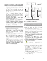
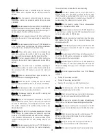
5.2.6. Relay COM port. Connector (X32).
•
The communications line (COM) is a very low voltage
circuit of safety. To preserve the quality, it must be
installed separate from other lines that have dangerous
voltages (power distribution line).
• The relay communication port provides digital signals in dry
contacts form with a maximum applicable voltage and current
of 6 A 30 V DC or 6 A 100 V AC. This channel makes possible the
dialogue between the UPS and any other machines or devices,
through the DB9 male connector
(X32)
.
Pin nr
Relay
Type of signal
Contact by default
N.C.-N.O.
1
Shutdown
-
2
Shutdown signal –
-
3
RL5
Configurable ((OPTIONAL)
N.C. or N.O.
4
RL2
Discharge - Mains fault
N.C.
5
RL1 to RL5
Common
-
6
RL1
Equipment on Bypass
N.O.
7
RL3
Low battery
N.O.
8
RL4
General alarm
N.O.
9
RL2
Discharge - Mains fault
N.O.
N.O. and N.C.: Normally opened and closed contact
respectively.
It changes its status, when the corresponding alarm is
triggered.
Table 2.
Relay interface alarm pin-out, DB9 connector
(X32)
.
• The base of front door
(PF)
has a slot to facilitate the entering and
way out of the communication cables inside the UPS. Watch to not
trap them between the door and cabinet when closing it.
5.2.7. RS-232 and RS-485 COM ports. Connector (X31).
•
The communications line (COM) is a very low voltage
circuit of safety. To preserve the quality, it must be
installed separate from other lines that have dangerous
voltages (power distribution line).
• In the same DB9 connector there are supplied both communication
ports of the equipment, the RS-232 and RS-485. Both ports cannot
be used at the same time, because they are mutually exclusive.
•
Both channels are used for connecting the UPS with any
machine or devices that has this standard bus.
The RS-232 consists of the transmission of serial data, so it is
possible to send a large amount of information through a
communication cable of just 3 wires.
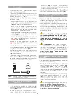
• Physical structure of the RS-232.
Pin 2. RXD. Serial data reception.
Pin 3. TXD. Serial data transmission.
Pin 5. GND. Ground signal.
• Physical structure of the RS-485.
Unlike other serial communication links, this uses only 2 wires
(pins 4 and 9 of the female DB9 connector) to make the dialogue
among the systems connected to the network. The
communication will be established by sending and receiving
signals in differential mode, which gives the system great
immunity to noise and a long range (approx. 800 m).
Pin 4. Output signal A (+) of the RS-485.
Pin 9. Output signal B (–) of the RS-485.
• Communication protocol.
The communication protocol used is «MASTER/SLAVE» type.
The computer or computer system («MASTER») asks about a
certain data, and the UPS («SLAVE») answers immediately with
the required data.
If this communication way, is going to be used, ask for the
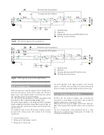
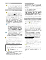
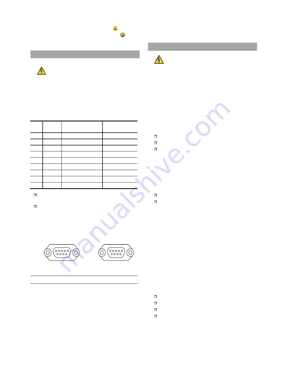
5
1
(X31)
9
6
1
5
(X32)
6 9
pro
tocol IN467*00.
Firstly the communication channel of the computer will be
programmed with the same parameters as the communication
channel of the UPS.
Then we will be ready to start the communication and therefore
send to the UPS the first question.
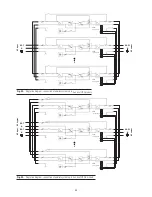
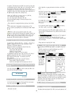
Fig. 30.
DB9 connector
(X31)
and
(X32)
.
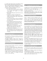
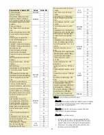
• By default the equipment is supplied with 4 signal relays with
a preset programming (see chart 2), which can be modified at
factory or by the
S.T.S.
under request. Chart 6 shows all the
alarms that can be set to any relay. A fifth relay can be supplied
as an option and under request, which can be defined in the
purchase order.
Also, there is a «Shutdown» input that allows turning off the
inverter, when there is a voltage between (5÷ 12 V) at this input.
• The most common use of these kinds of ports is to supply the
necessary information to the file closing software.
If there is any problem meanwhile communicating, it will be
advisable to repeat the initialization sequence of the channel.
• The communication parameters of the RS-232 and RS-485 are:
Baud rate: 1200, 2400, 4800, 9600 or 19200 Bauds.
Nr of data bits: 8 Bits.
Nr of stop bits: 1 or 2 Bits.
Type of parity: Even, Odd or None.
• The base of front door
(PF)
has a slot to facilitate the entering and
way out of the communication cables inside the UPS. Watch to not
trap them between the door and cabinet when closing it.


