38
˙
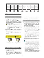
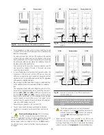
If the UPS connects to external battery cabinet, set the fuse holder
switch of the battery cabinet (Q8) to «On».
˙
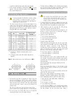
If the power supply you use to supply the UPS has a general switch
.
Set the general switch of the header board to «On».
˙
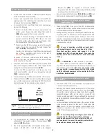
Turn the input switch (Q1a) to «On» position. The Display of the
Control Panel (PC) will be turned on automatically.
˙
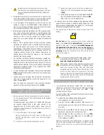
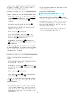
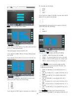
If the following alarm message appears on the Control Panel
Display,
.. and also an audible alarm comes on, the UPS cannot be started,
because of incorrect input phase sequence. Disconnect the input
switch (Q1a) and the general cut-off of the header board, swap the
phases of the input terminals of the UPS according to the labelling
and repeat the start-up process described up to now.
˙
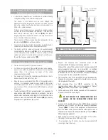
In units with separate Bypass (UPS-B), also turn the Bypass switch
(Q4) to «On» position.
˙
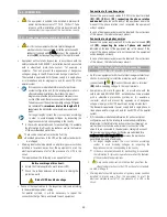
If the following alarm message appears on the Control Panel
Display,
... and also an audible alarm comes on, the UPS cannot be started,
because of incorrect input phase sequence. Disconnect the Bypass
switch (Q4) and the general cut-off of the header board, swap the
phases of the input bypass terminals of the UPS according to the
labelling and repeat the start-up process described up to now.
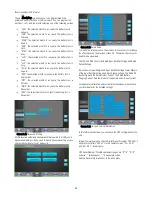
Start up the inverter through the keypad of the control panel.
a.
Select ”CNTL”
b.
Select ”ON/OFF”
c.
Start up unit information will appear. Select ”Yes”.
Then, the inverter and rectifier will start.
˙
Once the rectifier is completely working, it starts a process of
equalization (DC bus voltage starts to equalize with battery
voltage). After a few seconds (depending on the battery level), an
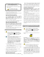
alarm message appears like this.
…
it displays that the equalising process has been finished, and
IN THIS MOMENT ONLY is when the battery fuse holder switch or
switch of UPS (Q3) can be turned on.
DO NOT TRY to close any battery fuse holder switch at any other
moment, because this operation could damage the equipment and/or
cause possible accidents. They can only be turned on by following the
quoted previous steps.
Turn on the output switch (Q2) to “On” position. The system will
supply voltage at the output terminal.
If you want to start up a parallel system, you should follow the steps
below
.
Close the mains circuit breaker to provide power to the input of the
each UPS in the system.
Turn the input switch (Q1a) to “On” position for each UPS in the
system. Each display of the Control Panel will be turned on
automatically. Do not close any other switches at this time.
Repeat the start-up process on LCD Touch Screen as what mentioned
before.
• After 30 seconds, the inverters and rectifiers of each UPS will start
up, but they will not supply voltage at their output yet because the
output switches are not turned on yet.
The first UPS to start up the inverter will be set as «Paral. Mst. Byp»
initially, the one with the highest address as «Paral. Slv. By.Rsv» and
the rest, if there are any as «Paral. Slv. By». Obviously in those
systems with two equipment, the «Paral. Slv. By» will not exist.
The UPS hierarchy relating to the rest of equipment of the system is a
dynamic depending on the status of the rest of the equipment.
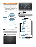
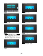
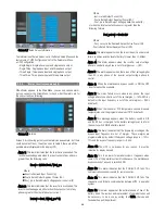
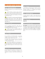
To check the hierarchy of the UPSs (parallel status), is needed to go
back to main screen in each equipment marked in the picture below
(Screen 00):
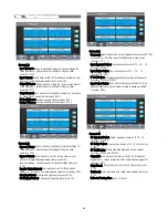
Where:
–– «Paral. Mst. Byp» Bypass master of the parallel system. By default,
it is the first UPS that starts up the inverter by the previous
established procedure.
–– «Paral. Slv. By.Rsv» Reserved bypass slave. Initially corresponds to
the equipment with the highest address less the one with «Bypass
Master». In case of fault in the Master, it will take its functions.
–– «Paral. Slv. Byp» Bypass slave of parallel system (for systems with
more than two equipment only). It will become as «Reserved bypass
Slave», when it works as «Bypass Master». In those systems with
more than three equipment in parallel, the hierarchy of «Reserved
bypass Slave» will be taken by the highest address among the
«Bypass Slave».
–– «Paral. Mst. Volt» Voltage Master of parallel system. By default, it
is the first UPS running on normal mode (inverter in operation) that
the output switch (Q2) is turned «On».
–– «Paral. Slv. Vt.Rsv» Reserved voltage slave of parallel system.
Equipment on normal mode (inverter in operation), that the output
switch (Q2) has been turned «On» in 2nd place or subsequently (after
«Paral. Mst. Volt» or «Paral. Mst. Vt.Rsv»). Initially, it corresponds to
the equipment with the highest address less that one with «Voltage
Master». In case of fault in the Master it will take its functions.
–– «Paral. Slv. Volt» Voltage Slave of parallel system (systems with
more than two equipment only). Equipment on normal mode (inverter
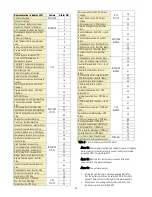
! MAINS PHASE ROT. UPS START INH.
! BYPASS PHASE ROT. UPS START INH.
!BATT. SWITCH OPEN SWITCH IT ON

