If the adjustable frequency drive is in alarm mode or in an
overvoltage situation, the mechanical brake immediately
cuts in.
In the vertical movement, the key point is that the load
must be held, stopped, controlled (raised, lowered) in a
perfectly safe mode during the entire operation. Because
the adjustable frequency drive is not a safety device, the
crane/lift designer (OEM) must decide on the type and
number of safety devices (e.g. speed switch, emergency
brakes, etc.) to be used, in order to be able to stop the
load in case of emergency or malfunction of the system,
according to relevant national crane/lift regulations.
L1
L2
L3
U
V
W
02
01
A1
A2
130BA902.10
Drive
Output
relay
Command Circuit
220Vac
Mechanical
Brake
Shaft
Motor
Frewheeling
diode
Brake
380Vac
Output
Contactor
Input
Power Circuit
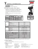
Figure 2.19 Connecting the Mechanical Brake to the Adjustable
Frequency Drive
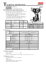
2.4.6 Serial Communication
Connect RS-485 serial communication wiring to terminals
(+)68 and (-)69.
•
A shielded serial communication cable is
recommended
•
See
for proper
grounding
61
68
69
+
130BB489.10
RS-485
Figure 2.20 Serial Communication Wiring Diagram
For basic serial communication set-up, select the following
1.
Protocol type in
8-30 Protocol
.
2.
Adjustable frequency drive address in
8-31 Address
.
3.
Baud rate in
8-32 Baud Rate
.
•
Two communication protocols are internal to the
adjustable frequency drive. Follow the motor
manufacturer wiring requirements.
Danfoss FC
Modbus RTU
•
Functions can be programmed remotely using
the protocol software and RS-485 connection or
in parameter group 8-** Communications and
Options.
•
Selecting a specific communication protocol
changes various default parameter settings to
match that protocol’s specifications along with
making additional protocol-specific parameters
available
•
Option cards which can be installed in the
adjustable frequency drive are available to
provide additional communication protocols. See
the option-card documentation for installation
and instruction manual
2.5 Safe Stop
The adjustable frequency drive can perform the safety
function
Safe Torque Off
(STO, as defined by EN IEC
61800-5-2
1
) and
Stop Category 0
(as defined in EN
60204-1
2
).
Danfoss has named this functionality
Safe Stop
. Before
integration and use of Safe Stop in an installation, perform
a thorough risk analysis to determine whether the Safe
Installation
VLT
®
AutomationDrive Instruction
Manual
2-12
MG33AM22 - VLT
®
is a registered Danfoss trademark
2
2
Содержание FC 300
Страница 1: ...MAKING MODERN LIVING POSSIBLE Instruction Manual VLT AutomationDrive FC 300 0 25 75 kW ...
Страница 2: ......
Страница 8: ...Contents VLT AutomationDrive Instruction Manual MG33AM22 VLT is a registered Danfoss trademark ...
Страница 14: ...Introduction VLT AutomationDrive Instruction Manual 1 6 MG33AM22 VLT is a registered Danfoss trademark 1 1 ...
Страница 62: ...Status Messages VLT AutomationDrive Instruction Manual 7 4 MG33AM22 VLT is a registered Danfoss trademark 7 7 ...
Страница 109: ...Index VLT AutomationDrive Instruction Manual MG33AM22 VLT is a registered Danfoss trademark 12 5 ...
Страница 110: ...www danfoss com drives MG33AM22 130R0300 MG33AM22 Rev 2013 03 12 ...