


V
IXEL
I
N
S
PEED
™ SAN S
TORAGE
S
WITCH
M
ODEL
375
C
HAPTER
3 S
WITCH
M
ANAGEMENT
U
SER
’
S
G
UIDE
EMBEDDED
IN
THE
FUTURE
OF
STORAGE
48
M
ONITORING
THE
S
WITCH
The Vixel InSpeed™ SAN Storage Switch Model 375 provides several options for monitoring the
switch status and port information. This section describes how to view switch status, the event
log, port information and utilization, and port diagnostics.
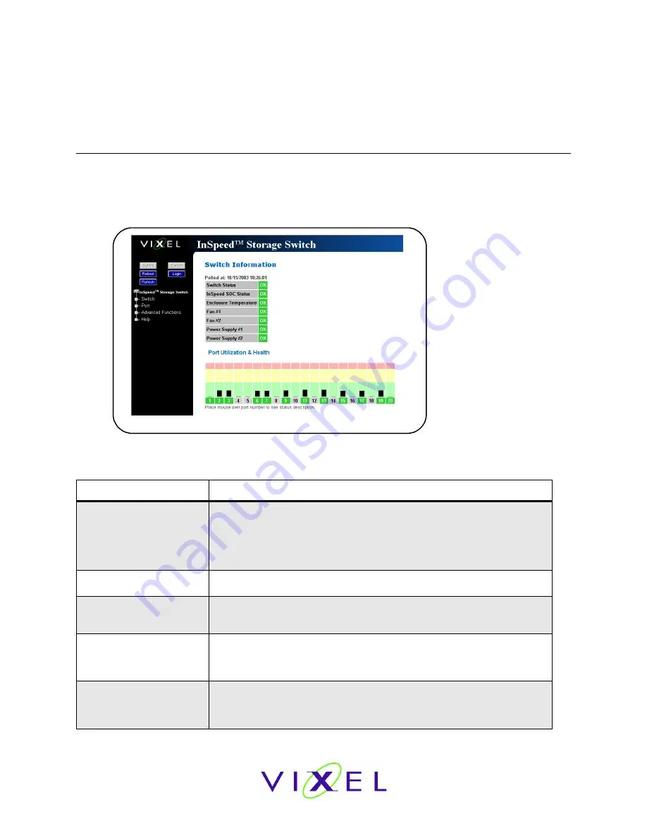
Viewing Switch Status
The Web Manager’s home page is the Switch Information page. This page is displayed first when
the Web Manager is opened and shows general switch information, including switch status, fan
and power supply operational indicators, and port health and utilization.
This page continually refreshes to guarantee that the most current switch status is displayed. To
return to this page at any time, click the
InSpeed™ Storage Switch
menu item.
Switch Information
Current status is provided for the following items.
Item
Status Indicators
Switch Status
OK (green)–the switch unit is operating normally.
Fault (red)–one or more of the ports has failed, the internal temperature
has exceeded acceptable levels, or another error has occurred. Errors
appear in the event log. The switch will continue to operate; however,
functionality may be impaired depending on the event that triggered the
error. Regardless of the cause, the switch requires immediate attention.
InSpeed SOC Status
OK (green)–the switch chipset is operating normally.
Fault (red)–the switch chipset’s selftest has failed.
Enclosure Temperature
OK (green)–the switch temperature is within the normal operating range.
OverTemp (red)–the enclosure temperature has exceeded the
recommended operating range.
Fan #1
OK (green)–the fan unit is working properly.
Not Present (yellow)–the power supply/fan module has been removed.
Fault (red)–the fan unit has stopped operating. Verify that the power
supply/fan module is properly seated in the switch.
Fan #2
OK (green)–the fan unit is working properly.
Not Present (yellow)–the power supply/fan module has been removed.
Fault (red)–the fan unit has stopped operating. Verify that the power
supply/fan module is properly seated in the switch.
Figure 3-26: Switch Information page


