


V
IXEL
I
N
S
PEED
™ SAN S
TORAGE
S
WITCH
M
ODEL
375
C
HAPTER
3 S
WITCH
M
ANAGEMENT
U
SER
’
S
G
UIDE
EMBEDDED
IN
THE
FUTURE
OF
STORAGE
45
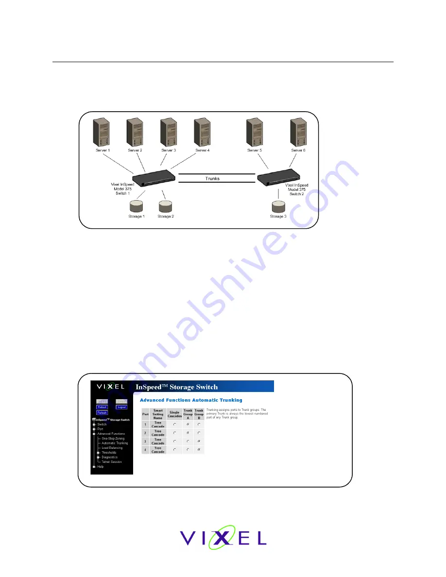
Automatic Trunking
Multiple links between switches are called “trunks”. Trunks provide higher bandwidth across
cascaded switches for systems incorporating multiple initiators. Each trunk can improve system
throughput and provide “failover” capability. A maximum of 4 trunks between each switch is
supported. Trunking is performed automatically when ports are configured properly. Figure 3-22 is
an example of Automatic Trunking.
Each trunk is part of a trunk group. A trunk group consists of two or more cascades between two
switches. There can only be one trunk group between two switches. Each trunk group contains a
primary trunk. All traffic flows through the primary trunk on a switch unless specified otherwise
using the Load Balancing feature. The primary trunk is always the lowest numbered port of any
trunk group.
If the primary trunk fails, the secondary trunk automatically becomes the primary trunk unless
otherwise configured. Multiple cascades also enable switch configuration for better performance
through load balancing (see “Load Balancing” on page 46).
The Automatic Trunking page enables users to configure trunking by defining trunk groups and
assigning ports to those groups. The Automatic Trunking feature is available when one or more
ports are assigned a String or Tree Cascade Smart Setting.
To configure Automatic Trunking:
1. Click
Advanced Functions > Automatic Trunking
.
The Automatic Trunking page appears.
2. Select a trunk group for each port by clicking the appropriate Trunk Group option.
3. When finished making changes, click
Submit
.
Figure 3-22: Automatic Trunking example
Figure 3-23: Advanced Functions: Automatic Trunking page


