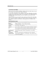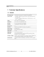
Technical Specifications
Analog Input
VT400 Technical Manual, Rev. A5
15
Doc
#
UM-VT400-EN
1.2 Analog
Input
Load cell excitation
±5V switched polarity or +5VDC with sense.
Connection
6-wire technique. Max 10 load cells 350Ohm each.
Signal range
•
-0.25 to 1.75mV/V (Gain=10).
•
-0.25 to 3.75mV/V (Gain=20).
Sensitivity
•
Approved scales: min 0.4µV / digit (VSI).
•
Non-approved scaled: min 0.1µV / digit.
Input amplifier
Input noise 0.3µVp-p, input bias current 10nA typical.
A/D Converter
Sigma delta 550.000 internal counts max. Conversion speed: 3, 7, 14, 28, 57,
70Hz (selectable).
Linearity
Within 0.002% of full scale.
Span temp coefficient
≤
2ppm/°C.
Zero temp coefficient
≤
2ppm/°C.
Long-term stability
0.005% of full scale per year.
1.3 Analog Output (Optional)
Power supply
External 24VDC, Main instrument PSU can be used.
Current or voltage
Selected via jumper JP1 on printed circuit board 761 (see section
7.4).
Current output
0-20mA or 4-20mA. Max load resistance 1K
Ω
(line + termination).
Voltage output
0.02-10V. Min load resistance 1K
Ω
(This is the default output).
Resolution
•
Internal: 16 bits.
•
External: 16 bits, or in accordance with regulation.
Linearity
Better than 0.01% of FSR.
Thermal stability
50ppm/°C typical.
Short-circuit
protection
25mA indefinite duration.

