Display, Keys and Menus
Setup Menus
VT400 Technical Manual, Rev. A5
27
Doc
#
UM-VT400-EN
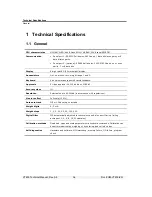
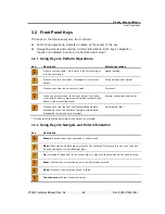
Function Description
Refer to
93
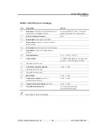
I/O test
. Display shows the status of input and outputs.
Section
8.2.3
94
Print buffer test
. An ASCII file (30h-7Fh) is output to the printer port, with
error control.
Section
8.2.4
96
Display characters received by COM ports
. Any character received by
COM 1 is echoed and displayed in ASCII hex on digits 1 and 2. Any
character received by COM 2 is echoed and displayed in ASCII hex on digits
5 and 6.
Section
8.2.5
99
Soft reset.
-
3.4 Setup
Menus
3.4.1
Accessing and Navigating Setup Menus
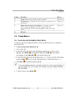
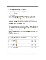
To enter the setup and calibration menus, either execute function 49, or follow the
procedure below.
To enter the setup and calibration menus:
1.
Turn on the unit.
2.
During the self-test routine, while all display segments are on (all 8 on the
display), press
( ) momentarily, followed by
TARE
( ) momentarily.
Alternatively, press
FUNCTION
(
), and access function 49.
3. If the PIN code is activated, the display shows
ACCESS
briefly. Type the PIN number
and then
( ) to get into the calibration menu. The display shows
SETUP
.
4. Use
TOTAL
(
) to step through the menus.
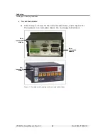
The menus displayed depend on whether jumper JP1 is in the sealed position or
not (see section
4.4). If it is sealed, the following menus are hidden:
Par
,
CAL
,
INIT
and
A-CAL
.
5. To enter a menu, press
( ).


