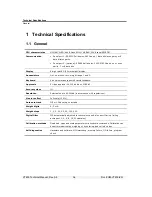


Display, Keys and Menus
Setup Menus
VT400 Technical Manual, Rev. A5
28
Doc
#
UM-VT400-EN
3.4.2
Menu Structure
Main menu
Submenu
Description
SETUP SETUP
1
Totalizer enable/disable and key locking.
SETUP
2
Serial port 1 parameters.
SETUP
3
Serial port 2 parameters.
SETUP
4
Tilt Switch parameters.
SETUP
5
Setpoint parameters.
Par
0.P, 1.P, 2.P, 3.P, 4.P, 5.P, 6.P, 7.P
General scale parameters with multiple values.
8.1, 8.2, 8.3, 8.4, 8.5, 8.6, 8.7, 8.8, 8.9,
8.A, 8.b
General scale parameters with two possible
values.
CAL S-CAL
(ZEro,
SPAN)
Standard-weights calibration dialog.
E-CAL
(ZEro,
SPAN)
Electronic calibration dialog.
STORE -
Permanently saves calibration data and exits
setup.
INIT -
Resets scale parameters, configuration and
calibration data to manufacturer defaults.
A-CAL
A.1, A.2, A.3, A.4, A.5, A.6, A.7, A.8
D/A analog output parameters.
3.4.3
Parameter Summary
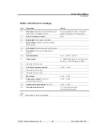
SETUP > SETUP 1 (General Operating Parameters)
Par. Description
Values
1.1 Enable
totalizer
. YES enables the totalizer. NO disables it.
0=NO 1=YES
1.2
(Reserved for future use)
1.3
Lock ZERO key
(
)
0=NO 1=YES
1.4
Lock TARE key
(
)
0=NO 1=YES
1.5
Lock P.TARE key
(
)
0=NO 1=YES
1.6
Lock PRINT key
(
)
0=NO 1=YES
1.7
Lock TOTAL key
(
)
0=NO 1=YES
1.8
Lock FUNCTION key
(
)
0=NO 1=YES


