Service Operations and Testing
Testing the Indicator
VT400 Technical Manual, Rev. A5
59
Doc
#
UM-VT400-EN
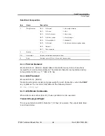
8.2.3
Testing Digital Input and Outputs (Function 93)
To test digital input and outputs (setpoints):
1. Access the function menu and select function 93.
2. The display shows the status of the inputs and outputs, as follows:
The first digit from the left displays data received on the digital input
channel.
The fifth digit from the left displays data sent on output 1.
The sixth digit from the left displays data on output 2.
3. Press
(
) to toggle output 1 on and off. When it is on, the data sent should
be displayed in the fifth digit. If the output connects to another device, check if the
signal was received.
4.
Press
TOTAL
( ) to toggle output 2 on and off. When it is on, the data sent should
be displayed in the sixth digit. If the output connects to another device, check if
the signal was received.
5. Connect a device to the digital input, and send a signal. See if the data appears in
the first digit.
8.2.4
Testing the Print Buffer (Function 94)
To test the print buffer:
Access the function menu and select function 94. An ASCII file (30h-7Fh) is
output to the printer port, with error control.
8.2.5
Testing Data Received on Both Serial Ports (Function 96)
To test data received on one or both serial ports:
1. Access the function menu and select function 96.
2. The display shows data received on COM ports, as follows:
The two digits on the left (first and second digits) show data received on
COM 1.
The two digits on the right (fifth and sixth digits) show data received on
COM 2.
3. Connect a PC or another device to one or both of the indicator’s ports, and begin
transmitting data. Watch the display to see if the data is received properly.

