


Troubleshooting
Errors, Causes and Remedies
VT400 Technical Manual, Rev. A5
60
Doc
#
UM-VT400-EN
9 Troubleshooting
The indicator has no serviceable parts. Authorized technicians may:
Respond to errors shown on the display (see section
9.1).
Check load cell connections (see section
9.2).
Check the power supply (see section
9.3).
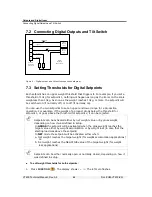
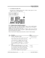
Check the digital input and outputs (see section
9.4).
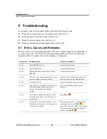
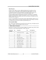
9.1 Errors, Causes and Remedies
When an error or an unexpected event occurs, the indicator displays the message
Err
xx
, where xx is the error code. The following table explains all the error codes and
suggests what to do when each error message is displayed.
Error code
Possible cause
Actions to be taken
Err 01
Faulty EPROM memory.
Contact manufacturer.
Err 02
Faulty CMOS RAM.
Contact manufacturer.
Err 04
Calibration data corrupted due to faulty
EEPROM.
Contact manufacturer.
Err 05
The scale is not connected properly, or the
analog-to-digital converter is faulty.
Check the scale, cable and connectors. If
these are okay, contact manufacturer.
Err 06
Insufficient power.
Check the indicator’s power supply.
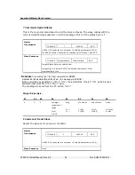
Err 07
Data memory is corrupted, either because
of extreme power supply transient or
because the totalizer has not been
cleared.
Input all operational data and clear
totalizer.
Err 15
The indicator has been powered on after
an irregular shutdown: A power failure or
a soft reset.
Press
ZERO
(
).
Err 20
The printer is not online because it is not
connected, not turned on, out of paper, or
for some other reason.
Make sure the printer is connected and
operational, and press
(
) to
retry. If you can’t bring the printer online,
and you would like to use the indicator
anyway, press
ZERO
(
).


