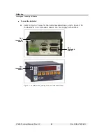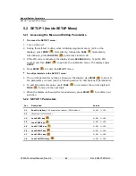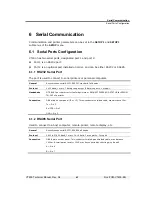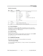
Display, Keys and Menus
Setup Menus
VT400 Technical Manual, Rev. A5
31
Doc
#
UM-VT400-EN
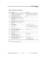
SETUP > SETUP 5 (Setpoints)
Par.
Description
Values
5.1, 5.2
Setpoint 1 output.
5.1=0 and 5.2=0: normal
5.1=1 and 5.2=0: no motion
5.1=0 and 5.2=1: error
5.3, 5.4
Setpoint 2 output.
5.3=0 and 5.4=0: normal
5.3=1 and 5.4=0: zero
5.3=0 and 5.4=1: net
5.6
Net / gross
for both setpoints.
0=net
1=gross
5.7
Normally open / closed
for both setpoints.
0=normally open
1=normally closed
A-CAL (Analog Output)
Par. Description
Values
A.1
Standard / custom zero and span
.
0 specifies that the scale should output 0mA at zero input and
20mA at maximum input (or 0V at zero and 10V at max).
1 opens a dialog, after
A.8
, that allows you to enter custom
zero and span values. Press
to confirm; the display
shows
0 XX.XXX
. Enter the D/A output at zero, in voltage or
mA, and press
. The display shows
F XX.XXXX
. Enter the
D/A output at maximum input, in voltage or mA, and press
.
0 = Standard (20mA max)
1 = User defined Zero and
Span
A.2
Normal or absolute AOUT mode.
Specifies what happens
when the displayed weight is negative: analog output is either
zero (normal mode) or the absolute value of the negative
reading (absolute mode). For example, if the display shows -
100.00, and absolute mode is set, AOUT=10mA. In normal
mode, AOUT=0mA, regardless of the negative reading.
0= Normal
1 = Absolute
A.3
Error output level
. Specifies whether scale errors should be
indicated as a low or high signal.
0 = Low (0mA)
1 = High (24mA)


